The Roll Centre of a vehicle has a large impact on handling but it`s something not many people fully understand.
A “roll center” (RC) is a theoretical point around which the chassis rolls when cornering and is determined by the design of the suspension. – That`s all well and good but it obviously goes out of the window as soon as the car is actually moving on circuit ! For the purposes of this post the calculations and reasoning are valid. 
I know there are chassis engineers who will point out I don`t mention the Centre Of Mass, you are correct, I don`t ! lol Whilst that is obviously relevant, this post is only about the effect of balljoint extenders on the Roll Centre.
I have had several messages asking where I bought my extenders. I ordered them from Noath Precision Engineering http://noath.co.uk/ who supplied a very well machined set built to my requirements.
With the aid of this fantastic online calculator at www.racingaspirations.com I will try and explain how Roll Centre is calculated on a vehicle with McPherson strut suspension. Double wishbone suspension is calculated slightly differently but the basic idea is the same.

A car with a ride height of 200mm and a stock suspension setup

Mark a 90Degree angle from the centreline of the strut to where it is connected to the topmount

Draw a line from the centre of the topmount at 90 degrees

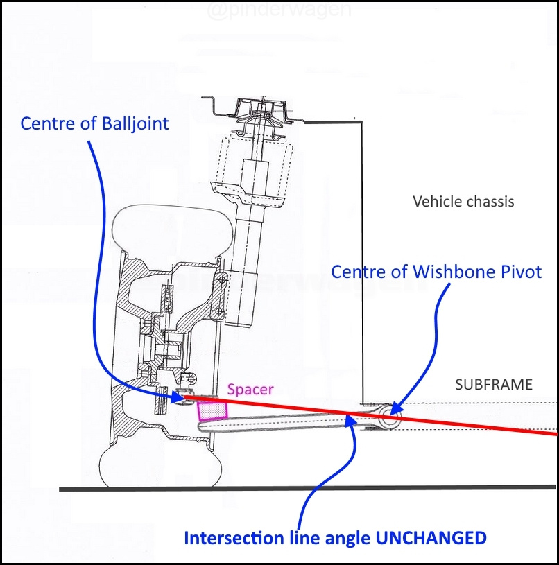
Draw a line from the centre of the Balljoint through the centre of the mounting point where the wishbone is bolted to the chassis / subframe
Where these 2 line meet is called the Intersection Point

Next a line is drawn from the centre of the tyre contact patch to the Intersection Point

Where the vehicle centre line crosses the contact patch > Intersection Point is the Roll centre.

On this example at stock ride height, the roll centre is above ground.

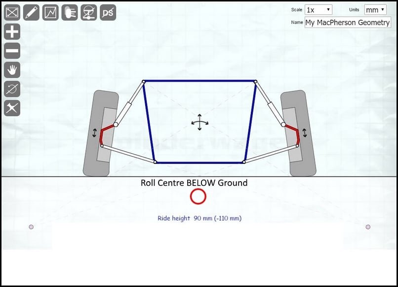
Using exactly the same process but by lowering the vehicle 110mm

The Roll Centre is now BELOW ground. This is not desirable.
We can`t easily move the chassis mounting points but we can lower the balljoint centre

Using exactly the same process on the lowered vehicle but with the balljoint lowered

The Roll Centre is now above ground again.

So what effect does the roll centre position have on handling ? Lowering the roll centre below ground causes increased understeer, increased body roll, more steering lock required to take a corner and lower feedback through the steering wheel.
I have never driven a MK2 Golf at a standard ride height so I`ve always assumed the handling of mine was typical of a MK2. Since fitting the plate diff I`ve found understeer increased especially in the wet and I have been struggling to address it. Speaking to friends who already have balljoint extenders I realised this could be the main cause of the issues I was facing.
There are a few different options available to correct the roll centre.
Custom made longer balljoints are available but I just don`t like the look of those at all for use on a track car. They may be fine but it wasn`t something I wanted to risk.
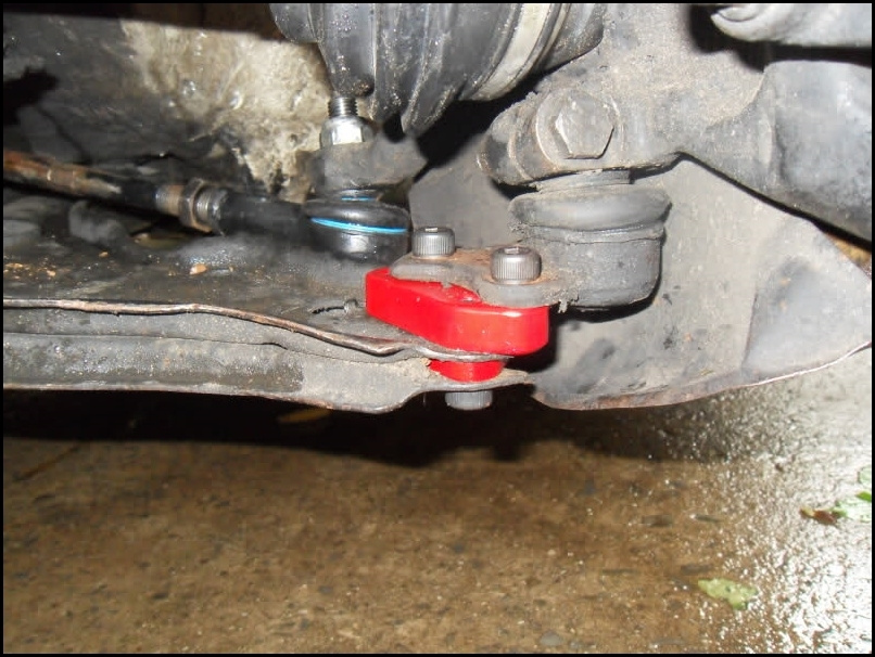
The female > Male bolt in extenders (on the right) were a common solution but the supplier of this particular type for the Golf is no longer making them.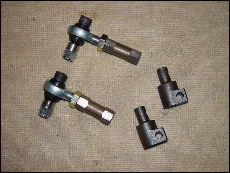
A good friend ran them for 10 years without issue but over time they suffered from fatigue and eventually failed.


Several people have struggled to understand why balljoint spacers or mounting the balljoint on top of the wishbone doesn`t actually do anything.
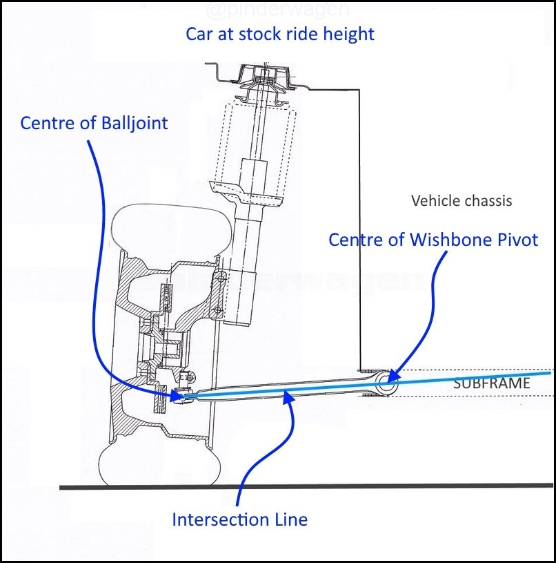
This is a typical car at stock ride height and running McPherson strut suspension. Original image created by Dave on ClubGTi

At standard ride height, the centre of the balljoint is higher than the centre of the wishbone pivot.
This is what you are trying to maintain when lowering the car.
Lowering the car has the undesirable effect of moving the chassis lower than the balljoint and excessive lowering results in the situation on this drawing where the wishbone is pointing upwards at the wheel end.
This is where all the confusion arises. The wishbone angle is a simple visual guide to see if the car is lowered too much.

To address the issue, people have fitted balljoint spacers or mounted the balljoint on top of the wishbone in the mistaken view this will address the problem.
I do understand that some spacers also move the balljoint outboard and forwards to modify the caster and camber. What is does NOT do is affect the roll centre.

The spacer is fitted between the balljoint and wishbone.
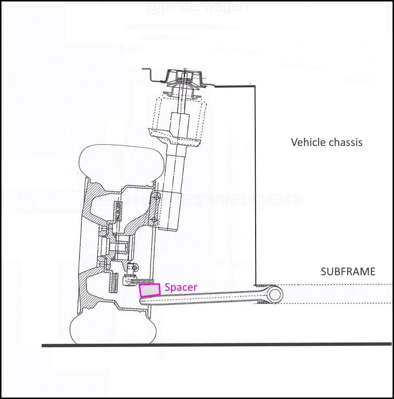
The wishbone is now lower at the wheel end and that is what people look at, thinking that the wishbone is now pointing down so assume the roll centre issue has been addressed.
This is incorrect.
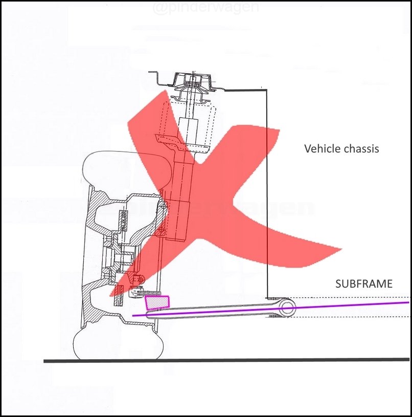
The Intersection line is completely unchanged.
The only options are to raise the wishbone pivot at the chassis end, which is difficult and often impossible.
The solution usually employed is to fit balljoint extenders.
To make it easier to understand I will show longer balljoints being used instead. This is not something I`m comfortable in actually using but they are shown to explain the theory. Balljoint extenders are a far better solution, but the effect on roll centre correction is identical.

The critical point is that the centre of the balljoint has been lowered.

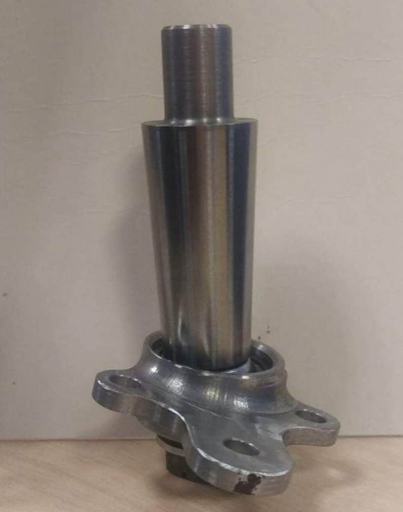
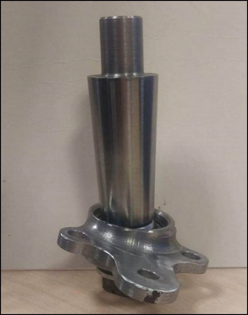
What I wanted to do was fit some weld in drop pins which connect to spherical bearings to replace the original balljoint completely.
I placed an order with Noath Precision Engineering http://noath.co.uk/ who supplied a very well machined set built to my requirements.
![]()
Because I run 6 degrees of Caster, the usual holders they make would run out of articulation under full lock. With the wheels straight ahead my hub is at a 6 degree angle from vertical, meaning the balljoint is already angled by 6 degrees. The Spherical only has a range of 9 degrees meaning I`d only had 3 degrees left.

The built in 6 degree offset to allow for my static caster can be seen pretty clearly on this photo. By having the bearing machined to match the Caster, it is centralised with the steering straight ahead allowing for more bearing movement over the full range of steering angle.

Obviously the pins aren`t just made from a length of standard mild steel bar that happened to be laying around in the workshop.
The Pins are EN19
EN19 is a high quality alloy steel with tensile strength.
With a combination of good ductility and shock resistance, EN19 is suitable for applications with very high loading such as engine gear boxes. Popular in the automotive sector it is possible to machine the material extremely accurately, in recent years EN19 has become an established material in the Oil & Gas sector. The material lends itself well to any application where strength is a primary consideration.
The housings are EN8
EN8- Steel- An unalloyed medium carbon steel. EN8 is a medium strength steel, good tensile strength.
The housings and combined Nut / Washer

The Retaining nuts have a built in washer. Initially these were supplied separately but I requested them as a `one piece` item which has a much better thread depth of more than 1 x the thread diameter.

The housings are obviously `handed` for the left and right side of the car.

Before welding the pins were fitted to the Hubs

On full lock the spherical was almost at the extent of it`s travel, but there was still a tiny amount of movement available meaning the bearing wouldn`t bind in normal use.
The pin has a radius where the larger diameter meets the pin, this meant the pin initially didn`t sit flush with the hub
By cutting a taper into the end of the hub, the pin sat flush.

Before welding the entire assembly was preheated

Tig welding using the correct filler rods.

To reduce any micro movement the top of the pin and the slot was also welded

The pin fully welded in place and allowed to cool naturally.

When fitted the pin is drilled and then a split pit used to lock it in place. I then painted everything with a galvanizing paint.
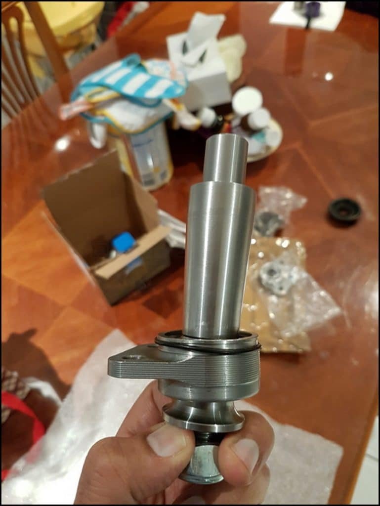
![]()
I have around 10mm clearance between the end of the drop pin and the inside rim of the wheel. On 15″ wheels this is the limiting factor in how long the pins can be.
Since fitting these pins I immediately noticed the Golf felt much more responsive to steering input. The steering feels lighter, body roll is reduced, understeer is reduced and I needed less steering angle to make a particular corner. I spent the first couple of laps touching the kerb at a corner apex as the usual amount of steering lock turned the car more than before.
Even in the wet the understeer I have been experiencing since fitting the plate diff is much less than before.
It does all of this because the roll centre is the point about which the car will roll about. Having it too long increases the lever length between it and the centre of gravity.Ball joint extensions bring it back up closer to the centre of gravity thus a shorter lever action and less body roll.
One thing to note is that Bumpsteer is directly affected by moving the lower balljoint. If you are lowering the balljoint the steering arm will also need lowering. It isn`t as simple as lowering the Balljoint 10mm means lowering the steering arm 10mm and bumpsteer needs to be measured and corrected after fitting any sort of balljoint extender.
There is no ‘one size fits all’ length of drop pin, it depends on the wheel size being used, existing geometry and hub type.
I never thought this particular modification would cause such a change in the handling of the Golf. Friends have been telling me for years I needed to address it but I didn`t see the need. I am happy to admit that was a mistake on my part and this is a very worthwhile modification to a lowered car.