I fitted the Gripper plate diff back in 2018.
The supplied breakaway-torque was 120Nm.
Test on the car
I check this fairly regularly so I can track the clutch plate wear. To check you simply jack up one side of the car with the gearbox in neutral. With a torque wrench and large socket on the hub-nut for the wheel in the air start off with the torque wrench on a low number and try to turn the hubnut. The torque wrench will click. Keep increasing the setting on the torque wrench and you`ll reach a point where instead of clicking, the wheel turns. That’s the breakaway point.
In my case, it had dropped to 70Nm after 12 months, which is down 50Nm from new.
I fitted some new plates to replace 4 worn ones and the breakaway-torque was back to 120NM. After 2 years it has dropped to 80Nm, which is 20Nm/year. 8 of the clutch plates are original and as I only had to replace 4 with new, there was less ‘new’ material to wear off the 4 replacements. I`ve found that the initial wear is when you see the largest drop-off in breakaway torque, after that it stabilises and drops off at a much slower rate once the clutches are `bedded in`.
Gripper rebuild service
Gripper offer a rebuild service where you post the diff back to them and they rebuild it for you.
They also suggest the following method of setting the preload.
“Generic Diff rebuilding.
Build the LSD as it came apart.
Allow 1.5-2mm total compression of the plate stack/springs. DO NOT FIT the internal wavey washers and thrust washers – so the side gears are loose.
Check the pre-load torque that you require and adjust the plate thickness up or down to change this. ALWAYS check that the gears are very loose.
Once the plate thickness is correct for the required preload, fit the THRUST WASHERS behind the gears to correctly engage the gears.
Check that the gears are just loose 0.25-0.5mm. If one gear is tight and one gear loose then change the plate thickness (left to right) to move the centre gear cluster over to make the gear fit correct. OR/also change the Gear Thrust washer for a different thickness. 2.25,2.50,2.75,3.0,3.25,3.5,3.8mm available.
Always check the gears are very slightly loose with the final washers – check again the preload.
Finally fit the Wavey Washers behind the gears. Check the preload again.”
I’ve done it myself and haven’t found it too difficult.
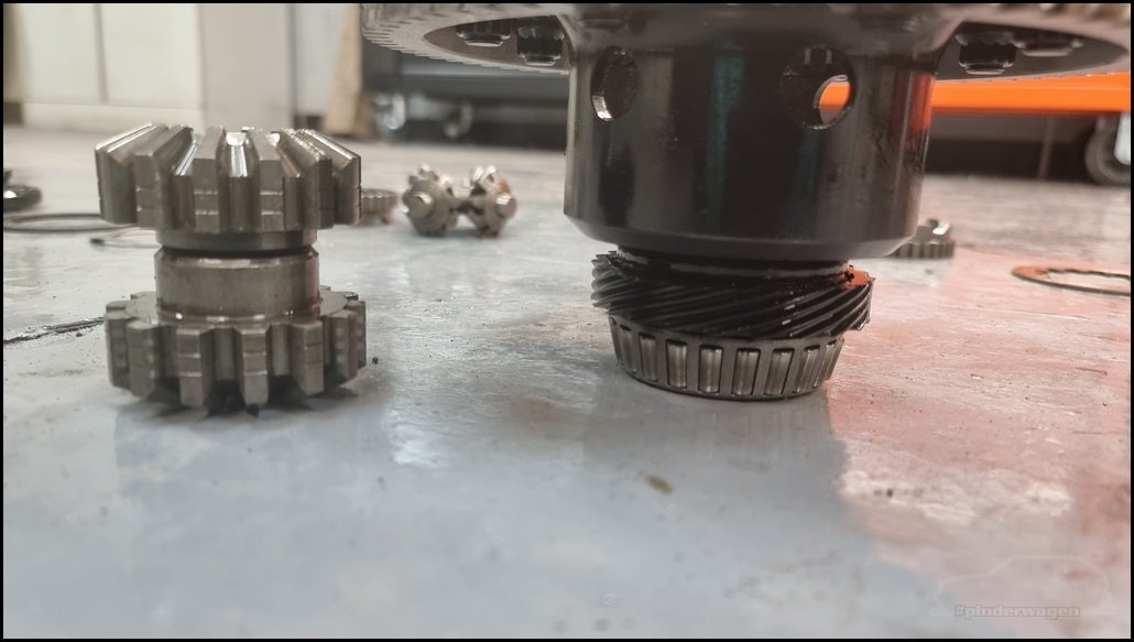
Once the diff is removed from the gearbox, you’ll need to test it. I took an old drive flange, fitted 2 bolts opposite each other into the thread and put it in the vice. You are just trying to hold the lower cup solidly.
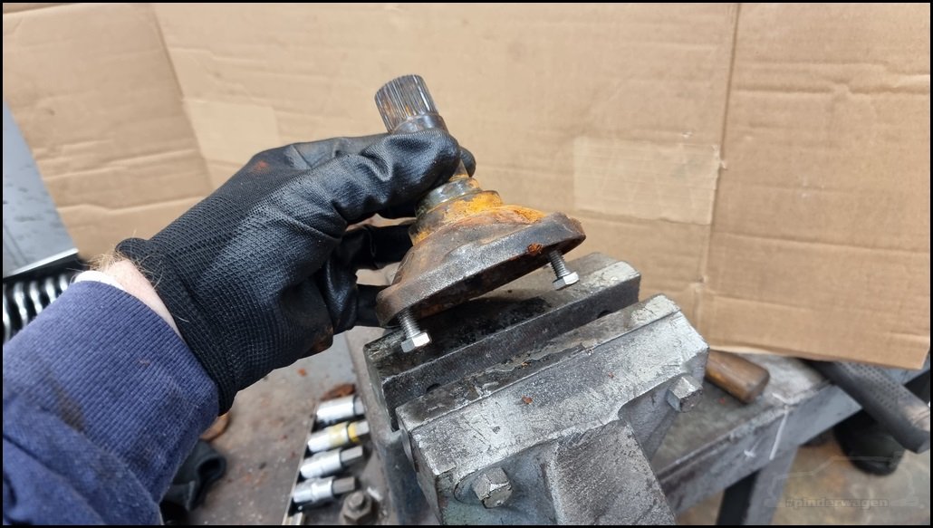

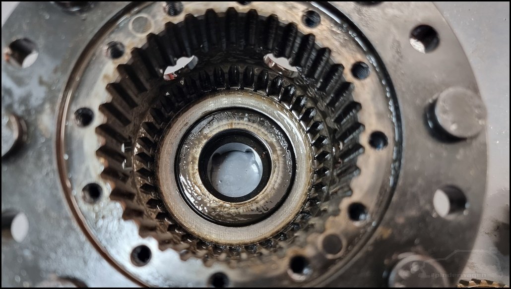
Sit the diff onto the splines. The crownwheel is removed on some of the photos as I was changing the final drive at the same time as servicing the diff.

For the other side you need to make an adapter. A piece of thick plate with a couple of holes to bolt to the drive flange and either weld a nut in the middle (which is easier) or if you don`t have a welder, use a 12mm bolt and 2 nuts.

Lock the bolt tight to the plate then double nut it to stop it loosening.

Initial testing
Fit the flange into the other half of the diff and then you’ll need your torque wrench and socket.

Start off with the torque wrench at say 40Nm, pull on it and it will click immediately. Increase the setting and keep trying to pull the torque wrench. You`ll get to a point where it just rotates the diff before clicking. That is the breakaway / preload torque. In this case it was 80Nm

This is a test where it was set at 102Nm. Note how it clicks, I rotate the handle to increase the setting and pull again until it doesn`t click.
Disassembly
To remove the cover, use a 5mm Hex drive. I use an impact gun but you can do it by hand.

The cover will probably stay in place with the bolts removed. There are 2 threaded holes machined into the cover for just this situation.

Use 2 of the removed cap heads and insert into these threaded holes.

As you wind the bolts down, it will break the seal on the lid and lift it away from the body.
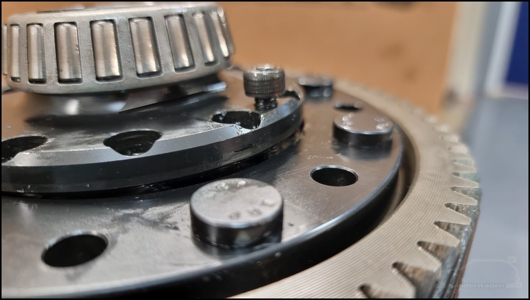
Immediately visible is the ‘wavy washer’ and Belle-Ville washer.
Remove the wavy washer

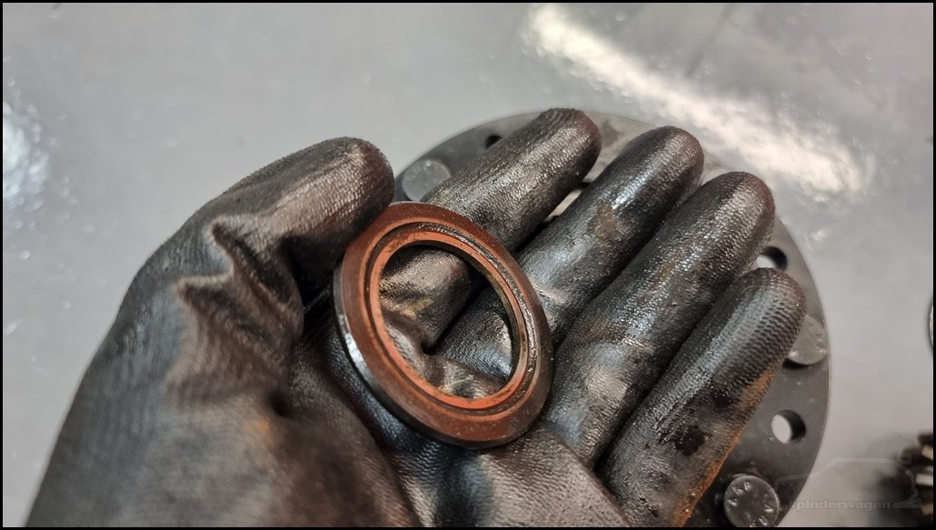
Remove the Belle-Ville washer, note the taper.

The thrust washer is next.

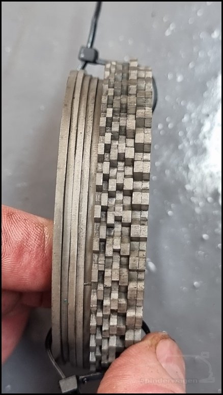
In my case, I have 6 clutches per side. 3 inner and 3 outer. Your diff may have 4 or even 8. The way the plates are stacked affects the way the diff acts. Mine is setup for track with alternating clutches, out-in-out-in-out-in. Some road setups have out-out-in-in-out-in for a less agressive operation.
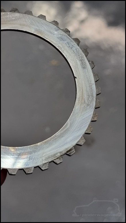
First is the outer toothed clutch.

It’s smooth and has no damage.

The inner clutch is grooved to allow the oil to get in between the plates.

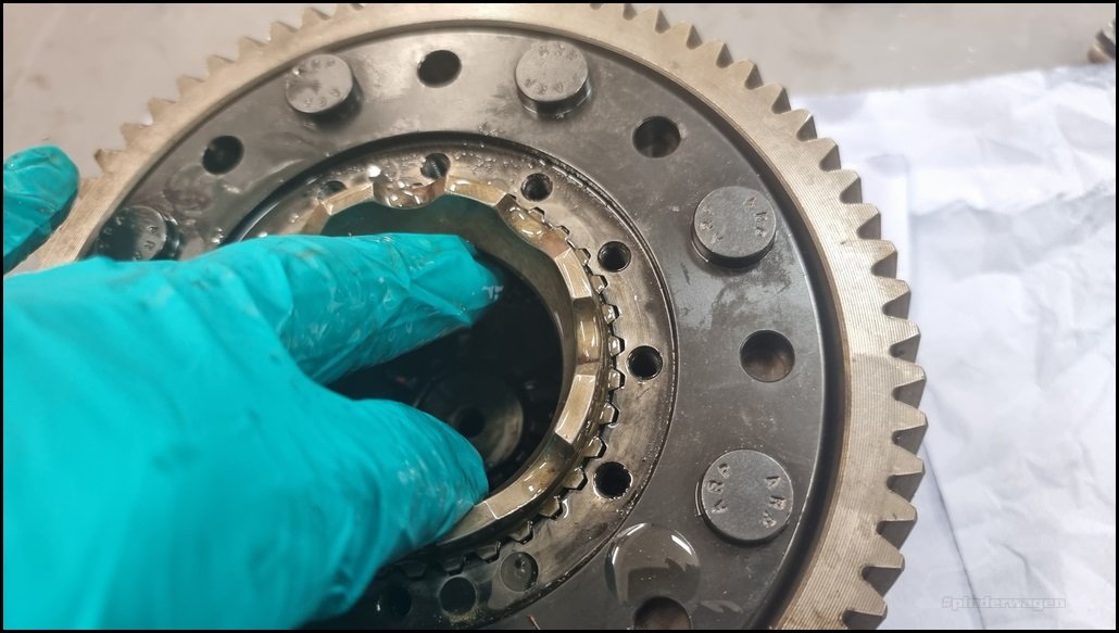
I remove the toothed inner drive cup. (I have no idea of the proper name 😉 )

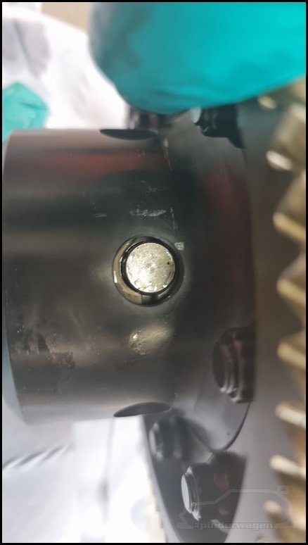
My drive cups are bolt in types, to there is a tapped disc that it located in the end of this cup and can be replaced if the thread is stripped or damaged.
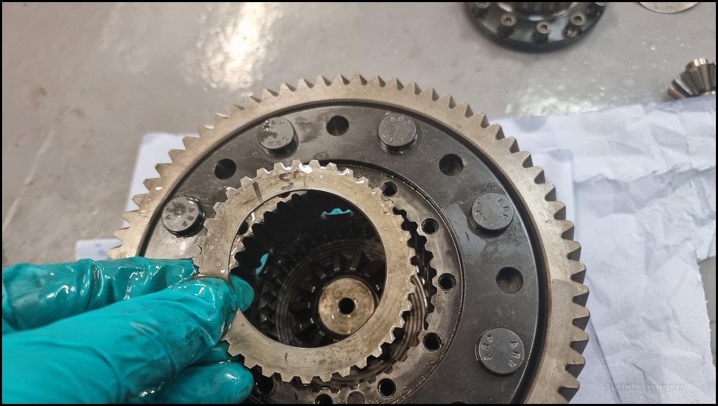
We’re now going to remove the inner clutch. I lay the parts out in the same order as I remove them to make re-assembly easier.


The 2nd outer clutch.


2nd inner clutch

3rd inner

I find using a couple of fingers inside the clutch, moved outwards, enables you to lift the plates out easily.

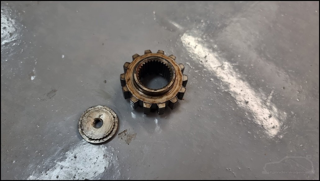
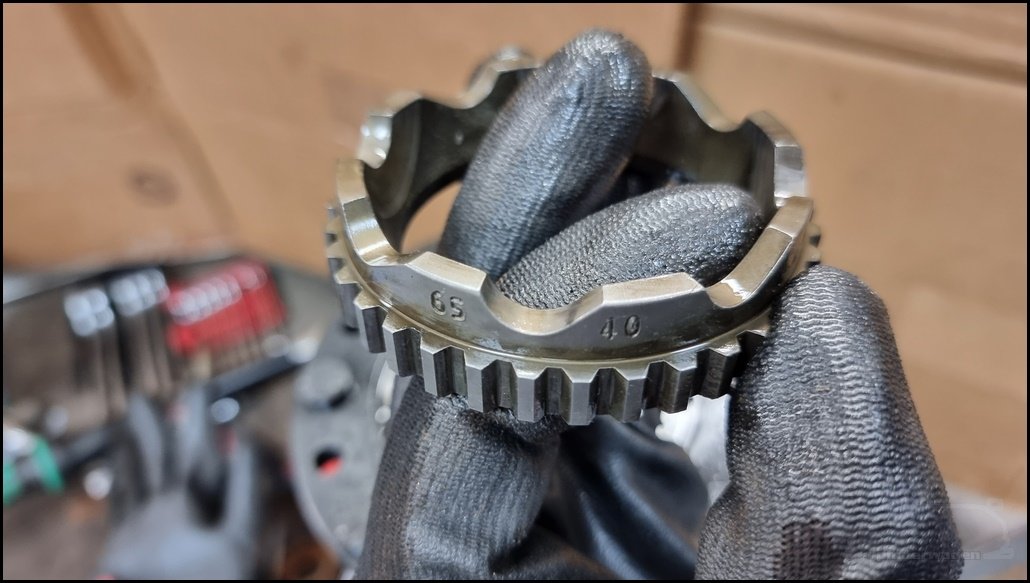
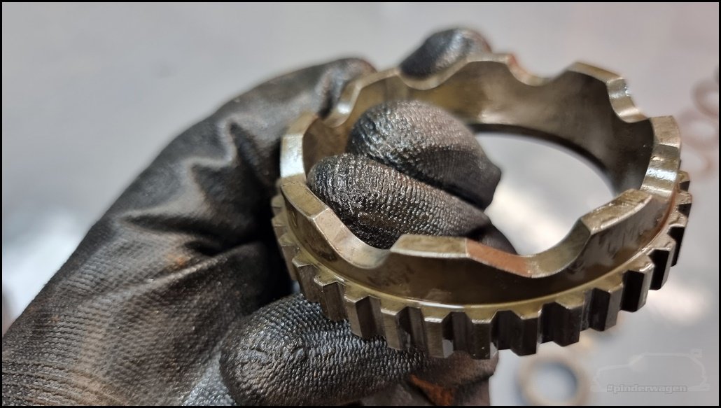
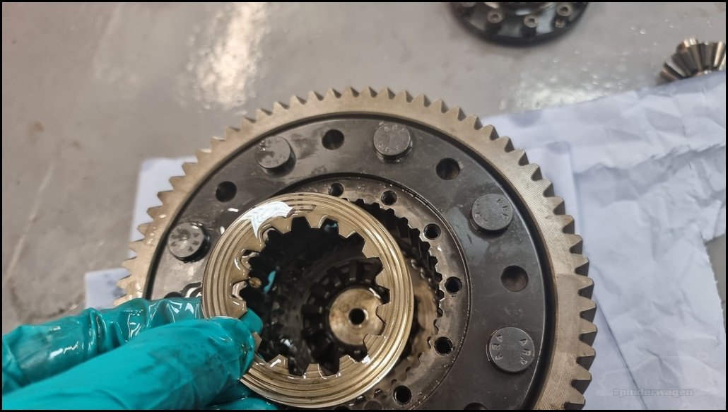
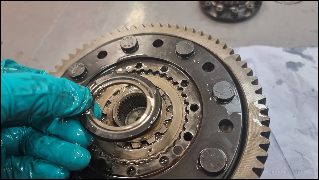
The planet driver is next. Don’t mix these up.
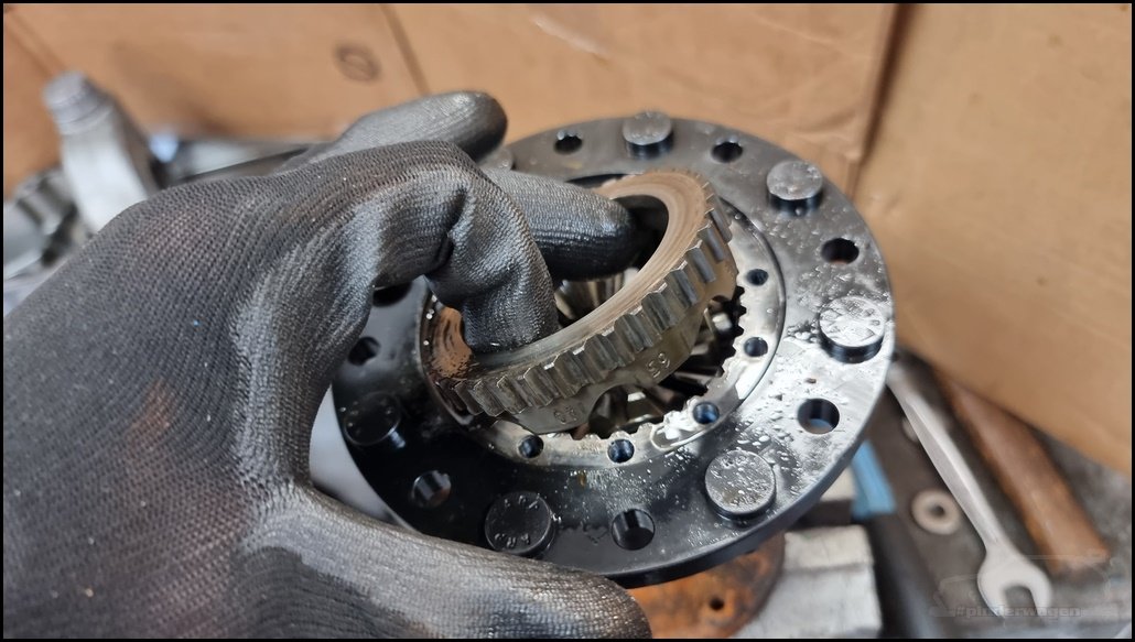
I run a 65/40 pair of ramp angles. You can see some light polishing on the 40 ramp.
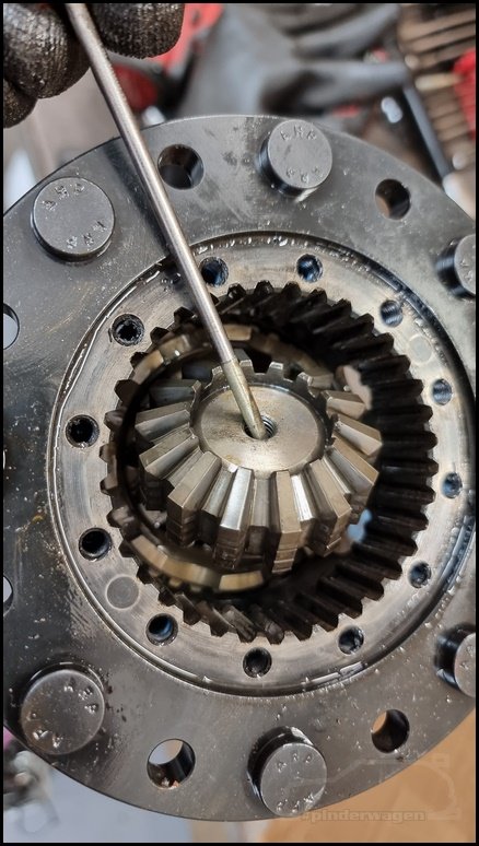
The planet gears are next.

These are a 2 piece item and can be refitted either way.


We now expose the other toothed inner drive cup.

It’s fiddly to lift out, I just used a screwdriver in the centre and lifted it out.
The lower planet driver is next.


Close inspection shows no cracking or damage to the ramps or inner face where the radius part of the planet gear touches.
The inner clutch is next.

Then the outer and repeat until all the clutches are removed.

With the clutches removed, you can now see the belleville washer and the top of the thrust washer.
Thrust washer removed

The other side
Belleville next. Again, note orientation of both those washers.
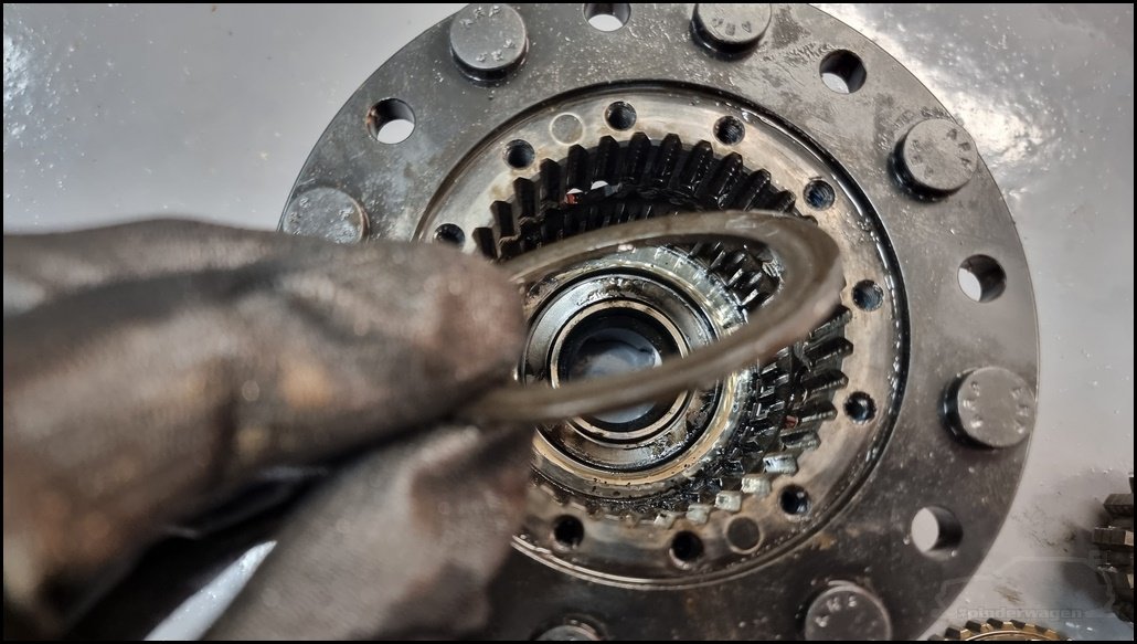
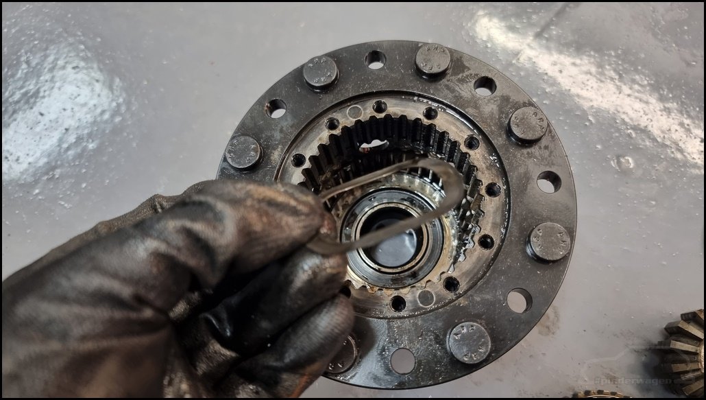
The final part is the wavy washer.

Remove it.
As my diff is in a synchro gearbox, there was some brass buildup in the outer clutch slots.

It can be scraped out with a small screwdriver easily enough and then cleaned

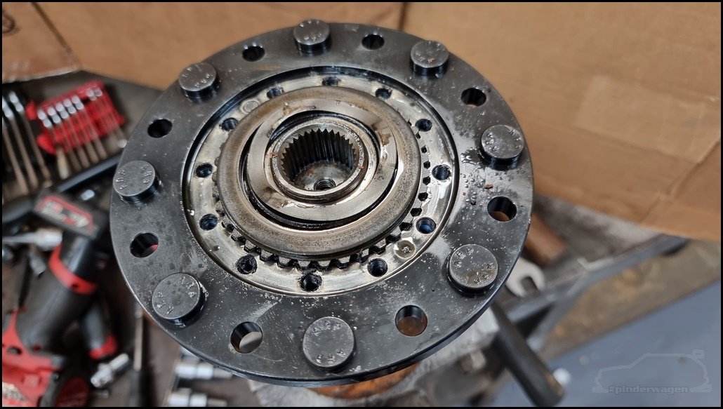
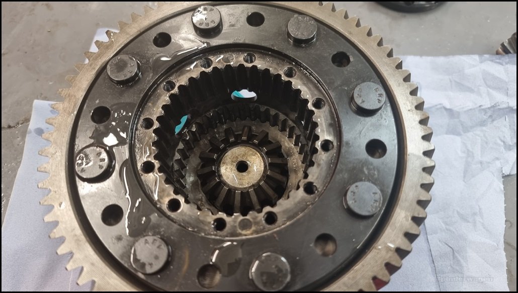
The Gripper diff laid out.


I bought a Gripper Small Service kit back in 2020.

It consists of several inner and outer clutches.

The clutches are different thicknesses. This is how you adjust the breakaway torque, by fitting thicker / thinner clutches.
A new clutch has a a slightly rough appearance, your finger nail can feel the texture.

A bedded in clutch is shinier.
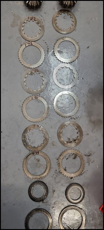
The full set of clutch packs

Measuring
A micrometer is easier, but it can be done with a vernier caliper. You need to measure each clutch accurately.

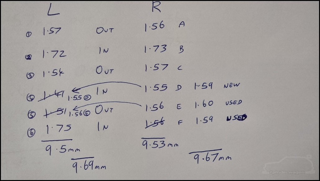
List each shim. I labelled one stack 1-6 and the other A-F Adding them up gives you the shim stack height.
9.50mm for one and 9.53mm for the other.

Adjust breakaway torque
To increase the breakaway torque, you increase the stack height. To lower it you reduce the stack height.
Don’t just fit new shims. This is an easy mistake but it’s much better to fit used clutches. The have their highest wear from new then stabilise. If the diff is built with clutches that have already been used, it will maintain breakaway torque for much longer.
By fitting used clutches, it will significantly extend the time between resets.
I replaced clutch (4) 1.41mm with (D) 1.55mm and (D) with a new clutch at 1.59mm
(5) 1.51mm was replaced with (E) 1.56mm. (E) was replaced with a previously used clutch 1.60mm
(F) 1.59mm was replaced with a previously used 1.59mm clutch from the last service.
Adding up the new stack heights showed a 0.19mm increase on one and 0.14mm on the other, whilst keeping each very similar to each other in total.
I wrote the size on each clutch with a sharpie, but some have worn off.
Rebuild
It is extremely important that the clutches are oiled during reassembly, otherwise the torque when testing will be much higher than it needs to be. I pour some gearbox oil into a tub and put the internals in the oil, removing them as I assemble it.

Refit wavy-washer.


Belleville washer is next, note the orientation.

Thrust washer next. The recess on the washer sits on the raised part of the casing thats on the inside of the wavy washer.

Outer clutch.

The toothed drive cup is different on the left or right. The height of the centre varies. If you get them the wrong way around you won’t be able to fit the cover.

This is how they are orientated in the casing for info.
By refitting the toothed inner drive cup, it allows the inner clutches to be refitted.

This site in the centre of the outer clutch.
First inner clutch

Outer
Inner

Last outer.

Finally last inner.
The Planet driver is ‘handed’, the RH goes in first.

Take note of the ramp angles used. The planet drivers have 2 sets of angles, I use 40/65, but the other set 30/60 can be used if required.

Align the outer teeth
Ensure the correct ramp angles line up with the holes in the casing.

Fit lower planet gear and shaft

Fit upper planet gear and shaft

LH Planet driver 40/65

LH Stamp

The end of the planet gear shaft should be visible in the viewing hole in the casing. If it isn’t you’ve probably built it up wrong.
The longer toothed inner drive cup sits on the planet gears, it may take a little bit of wiggling until it seats properly.

Onto refitting the clutches in the following order.
Inner.

Outer

Inner

Outer

Inner

Outer

The top outer clutch just sits lower then the housing

Thrust washer with the recess up.
Belleville washer

Wavy Washer

Top Cover

Tighten the M6 cap heads. No loctite at this point.

Bench testing attempt 2
The diff is now placed on the drive flange in the vice and the breakaway torque checked.
Common bolt and torque in Gripper LSD units.
M6 x 1.0 , Cap head, 12.9 grade various lengths used in our designs from 8mm to 19mm long.
Use Thread Locking agent (such as Loctite 243) & Torque to 20Nm (15 ft.lb)
For all other bolts, such as the CW location bolts, ALWAYS check the original manufactures information. For reference, you may consult the normal engineering charts below. This is only a guide, and you must confirm that these figures are suitable for you chosen bolt & application.
Always use Thread Locking agents.


I`ve had a few messages from people asking if they can support me in some way. I`ve set up a buy-me-a-coffee page for those of you who would like to do so  .
.
![]()