
Due to the track width and ride height changes I`d made over the years I was experiencing some bump-steer. What is bumpsteer you may ask ?.
Bumpsteer is when the steering wheel is kept in one position but the actual driven wheels turn and steer as the suspension goes over bumps causing the car to dart about as if you were moving the steering wheel. Hence the term `Bump Steer`
I measured the existing bumpsteer before making any changes and found I was getting 2mm of Toe out per side under maximum compression.
This GIF shows what bumpsteer actually looks like. Look at the white board bolted to the hub, keep an eye on the end nearest the bottom of the image, see how it moves in and out as the hub is lifted and lowered ? That`s bump steer. As the wheel goes over a bump, it compresses the suspension and the wheel turns without moving the steering wheel.
This clip goes Toe OUT when the spring is extended (I just did it to show what Bumpsteer is)

To remove it, you need to raise or lower the track rod where it joins the steering arm on the hub.
First off, remove the stock track-rod end and drill the taper hole to parallel 14mm

To ensure the new rod-end doesn`t foul under full extension or compression, lightly grind a taper to the top of the arm

A pair of suitable Female Spherical rod-ends bolt onto the existing track rod arm, with more than 1.5x Diameter of thread into the female hole. I`ve also fitted a small split washer at either side of the spherical to give extra clearance

Now you need to accurately measure the toe. This is the first method I used, but as you`ll see, I changed it later as this is very time-consuming and prone to error.
First of all, steering is centralised, springs removed from the suspension to allow the damper to move freely.
A parallel line is run down the side of the car (Yellow)
2 lines are dropped from a bar bolted to the hub (RED)

Hub height was measured

The distance from the front of the hub was measured to the line

Then the rear

Suspension lifted 5mm, the process repeated for the full damper travel.
The difference between the 2 is then plotted to show the total toe change over the suspension travel.

What does that tell me ? well, my measuring isn`t as accurate as I`d like and there is something odd going on. It should be a smoother line. (It turned out to be the ARB fouling the wishbone). Measuring between 2 flexible fishing lines is a pain in the backside, if you touch one, it moves and then you have to wait for it to stop moving before trying again. Then the ruler is only accurate to 0.5mm.
I had a max of 2mm Toe OUT under full suspension travel, that`s on one side only. That`ll be why it felt a little `twitchy` over the bumps at high speed…
That method was very laborious so I used the Longacre Bumpsteer gauge as a starter and made my own. I did a back-to-back check of the standard track rod end with the spring and ruler method compared to they board and vernier method and they were the same. Apart from the vernier method is far more accurate, repeatable and takes MUCH less time to do.
Bolt a flat sheet to the hub

Pivot another to the floor (I used Gaffer Tape on both sides as a `hinge)

At one end, have a 6mm bolt resting on the plate bolted to the hub. This keeps that distance constant

Mark measuring points on the fixed plate to ensure consistency of measurement

Using a vernier, measure through a hole to the back plate. This is remarkably repeatable. I did a set of readings 3 times and every measurement was within 0.2mm. Because the distance between the pivot and the measuring point was 24″, that`s an accuracy of just over 1mm if measured on a 15″ wheel.

To measure the height, I removed the wing (makes it all much easier), bolted a pole to the brake carrier and marked every 10mm. Then simply lifted or lowered the wishbone with a jack under the balljoint to every 10mm mark, then measured the distance between the plates using the vernier.

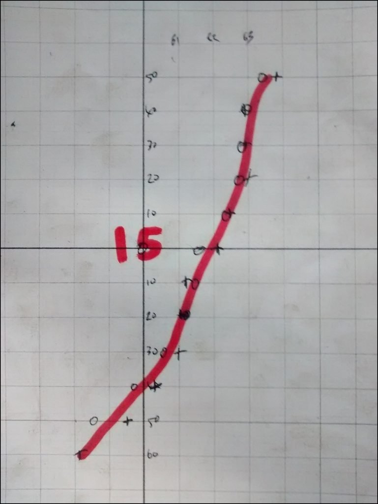
Plot on a graph, taking measurements when lifting AND lowering, then averaging the 2. This is the Spherical end with NO shims. The o & x are readings when raising & lowering the suspension, then a line-of-best fit was drawn between them.

Using a selection of M14 washers, lift the rod end and re-measure. Here I`m using 11mm of shims

If the line is at an angle, that shows the toe is changing under bump. A vertical (or as close to it as you can get) line shows the toe is not changing under bump, which is what I want.
Readings at 10mm

11mm

I have an issue where the readings were odd at the extreme end of the damper travel, I`d removed the small spring washers when testing and the washer was touching the rod-end causing load and a skewed reading.

13mm

15mm
As I wanted no bump steer, I went with 11mm.
As you can see, the toe doesn`t change as the suspension is lifted or lowered.

Repeat on both sides. For some reason I don`t quite understand the passenger side needs more shims.
That whole process took bloody ages, but I now have a repeatable toe change of under 0.3mm no matter when the suspension is (apart from the last few mm at each extreme)
Finish off by replacing the M14 Nut with an M14 Nyloc to ensure nothing moves.

This was the last travel toe change graph I made and I wasn`t sure why the ends both went the same way.

Version 2
Whilst the previous method I used was pretty accurate, it was time consuming. I looked around and thought the Longacre gauge was a good starting point.

Before going any further I removed the tie rods and centred the steering rack by measuring how much of the rack was showing at each end

It meant the steering wheel was slightly off, but I re-centred that on the splines.
I then set both tie rods to the same length and refitted them to the car.
Alignment was now checked and before adjusting any tie-rods, I loosened the rack and moved that as much as possible to get the same toe on either side with the same length tie-rods. The rack was then secured.
Unfortunately, I still wasn`t able to get the rack dead-central, I needed to lengthen the offside arm more than the nearside which I still don`t really understand the reason for
I made a bump-steer gauge. Some 10mm plate was chain drilled and then a 5×100 stud pattern drilled.

Now a hinged frame was made, this is weighed down with a couple of jerry cans to ensure it doesn`t move on the floor. These photos from before I drilled the hole out of the middle.

On the front upright, I fastened a 6mm bolt that was filed to a point.

A Dial Gauge was fastened to the other end of the plate.

You COULD put a dial gauge on each end of the plate, then take one away from the other. By having a fixed and, you can just measure the one end of the plate. If the wheel toes in, the dial gauge reading goes down as the plate moves towards the dti, Toe out and the plate moves away, increasing the the dti reading.
This gif shows what happens with extreme toe IN as the spring extends, I purposefully added too many spacers between the tie rod and the hub to show the effect.

Now if the tie rod is lowered too much and you get toe OUT under spring extension

The most obvious thing with this method is that you don`t need to measure every 10mm. It`s immediately obvious if you have toe in or toe out under bump. Then just add a spacer between the track rod and the hub and lift / lower the suspension again.
This is a FAR quicker and more accurate method then the previous `measure every 10mm` option. Initially you add a lot of washers and make a note which way the gauge goes. Then remove them all and note it goes the other way. Once you`ve done that it`s much easier to refer back and know if you need to add or remove washers to get zero movement
Unfortunately, I noticed a problem in that I was getting toe OUT under compression AND rebound. This is due to the Tie rod being too long.
This may help explain it a little.

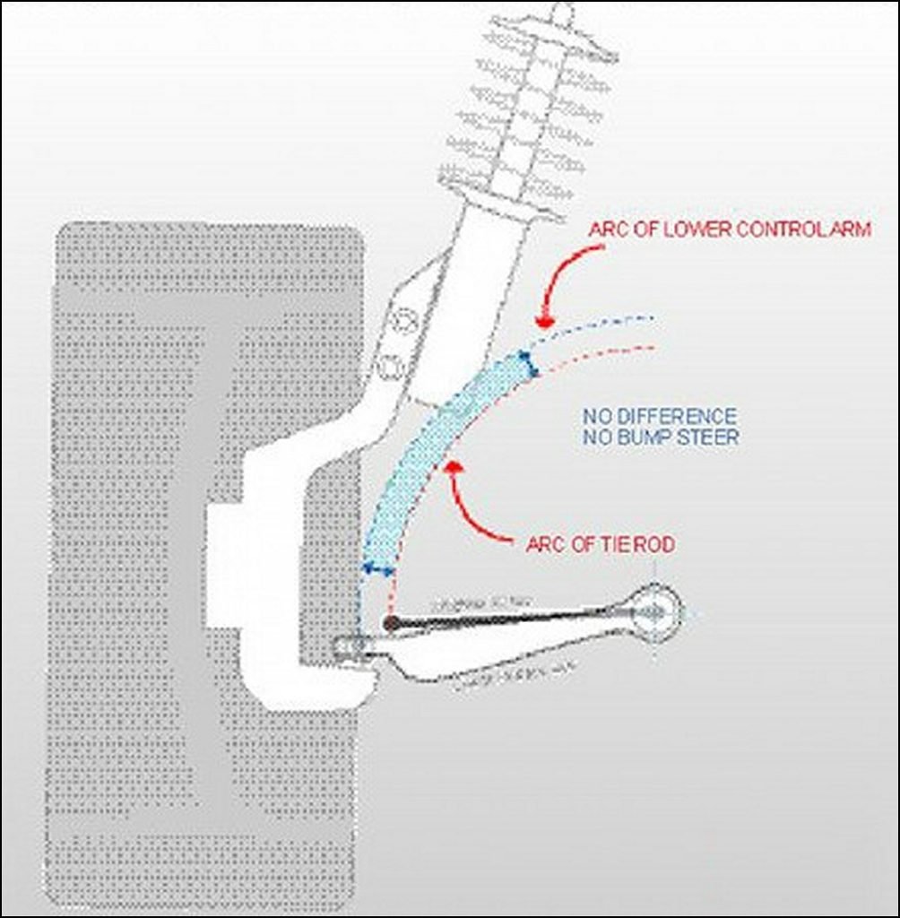
The best solution (apart from a wide steering rack) it to fit some tie-rod extenders like these.

I don`t have time to get some made, although I may do in the future. What I could do was space out the tie-rod 5mm. I don`t want to go any more as that would reduce the amount of thread securing the tie-rod to the rack.

I also moved the Lower Ball joint in by 2mm. This needed some material removing from the end of the wishbone, marked in green, as the LBJ was touching the metal.

Removed

By doing this, I reduced the length of the track rod by 7mm. Not a huge amount, but a step in the right direction. Some rack spacers are needed to completely remove any bump-steer.
Now I re-aligned the tracking and then re-measured the bump steer. By careful addition / removal of the spacers, I was able to get it pretty close. You can see how I get Toe out towards normal ride height then toe out AGAIN at the other suspension extreme. ie gauge goes one way, stops and then goes backwards

For a final check, the plate is marked every 10mm then the suspension lifted / lowered, with the dti reading being measured at every 10mm.

Around normal ride height, I have no bump-steer. Once I get towards the last 20mm of bump and rebound, I get up to 1mm of toe out under max compression and 0.8mm at full spring extension.
Not ideal, I would prefer none at all, however the bump steer has been far worse than this for the last couple of years so this is a marked improvement and it certainly felt less twitchy on the bumps after the first round of correction.
I made a few other suspension changes and restested the Bumpsteer, adjusting the height of the tie-rod using washers until it was almost completely removed.
Once I was happy with the height required I replaced the washers with a couple of misalignment washers and a single washer to get the 11mm adjustment necessary. The washers make setting up easy but I didn`t want to run with a stack of them once I`d settled on the necessary height.

When driving on track I no longer have noticeable bumpsteer and that tiny amount at each extreme just isn`t something I notice when driving.