At the end of 2016 I had a weird intermittent electrical misfiring issue and I was 100% it was wiring related. I`d rewired the ECU loom earlier last year but still retained part of the original loom for certain parts of the wiring.
This time I removed everything ECU related and wired it all up independently to a new set of relays and fuses. I can disconnect the car loom which means I won`t have wipers, brake lights etc but I can run the engine and IF I have an issue in the future it will make it easier to diagnose if I have an issue with the Car loom or ECU Loom.
Bought a load of wire. All the colours and gauge I needed.
I also wanted a wiring diagram that not only covered all the standard wiring but covered the extra circuits and connectors I`d added so I redrew the entire ECU wiring loom.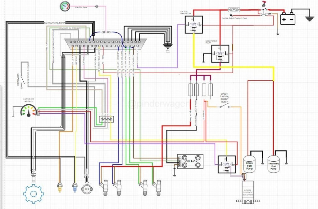
By having the loom in electronic format I can zoom in and out and also hide unwanted layers.
For example, this is the Injector supply and trigger circuit only. It makes it much easier to follow.
This is the Boost control layer
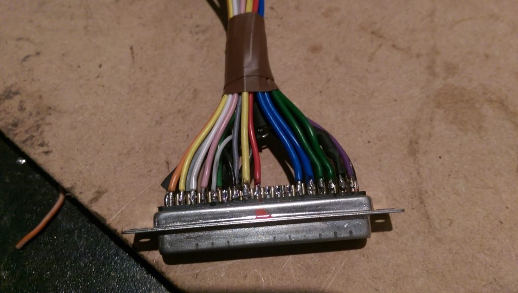
DB37 connector held in a vice whilst I soldered the individual wires to it. 
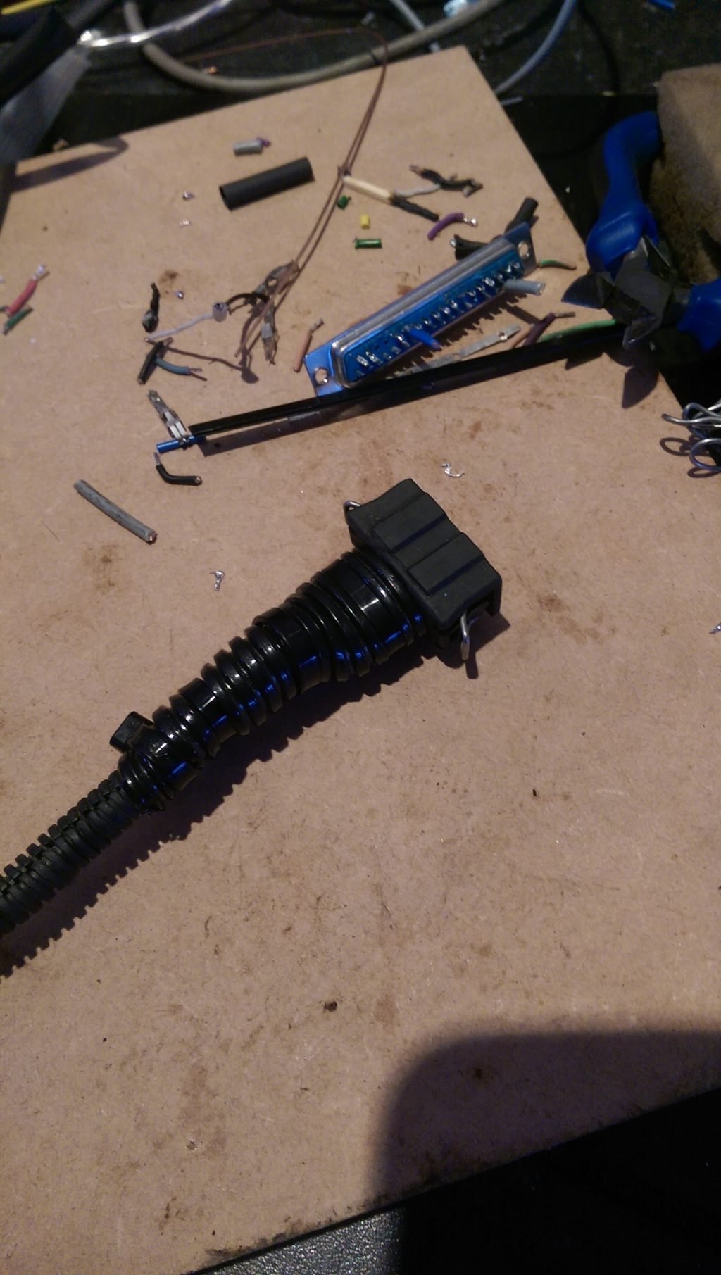
To enable the loom to be built off the car, I added connectors to every wires that I needed to connect to a fixed point. This is to the boost control solenoid for example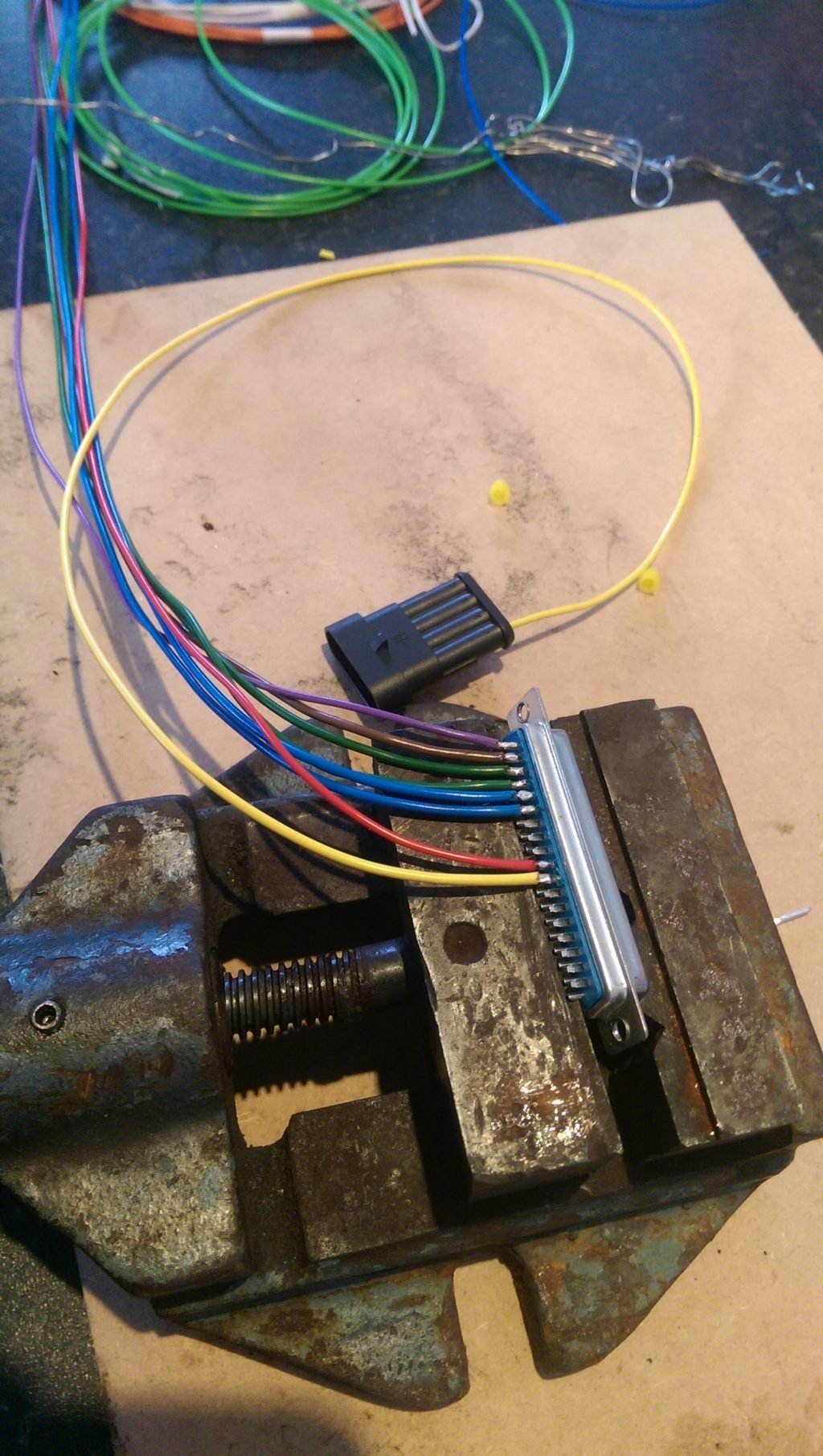
You can`t do this sort of job without a ratchet crimp tool, assorted crimps and various sizes of heatshrink.

Every crimp was electrically tested and then pulling the wire hard to ensure it was physically secure.

Obviously I wasn`t going to reuse any old connectors so I bought new crimp connectors for the injectors, Crank Position Sensor, TPS, Water temp and coilpack connections.

Clicked into place 
I wanted to be able to access and remove the ECU easily so installed 4 rivnuts into the floor

Test fit 4-rubber bobbins to the ECU

Bobbins screwed into the Rivnuts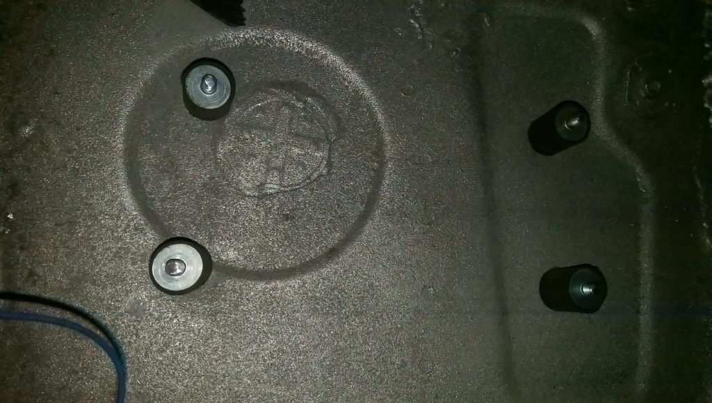
ECU Mounted to the Bobbins.
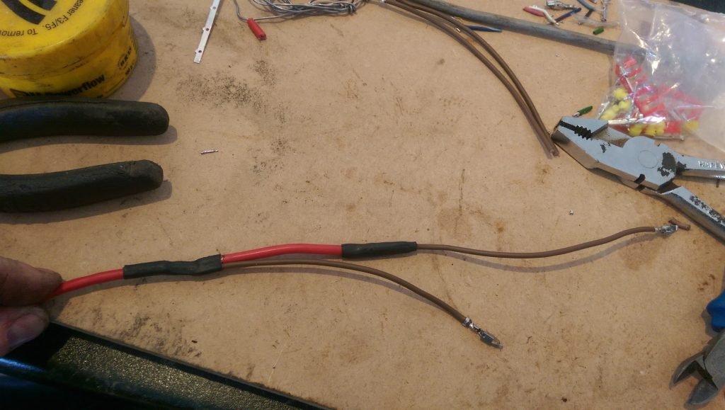
I know it`s overkill, but I ran the main injector feed in a thicker gauge wire and then short tails to each ECU 
Heatshrink with internal Glue was used on EVERY joint.
New connectors fitted.
New feed and triggers to the Coilpack plug with new connectors.
The ECU loom was built off the car and only required plugging in, a 12V fused feed to the Coilpack and Injectors and Ground connection and the 2 multi-plugs to other components.
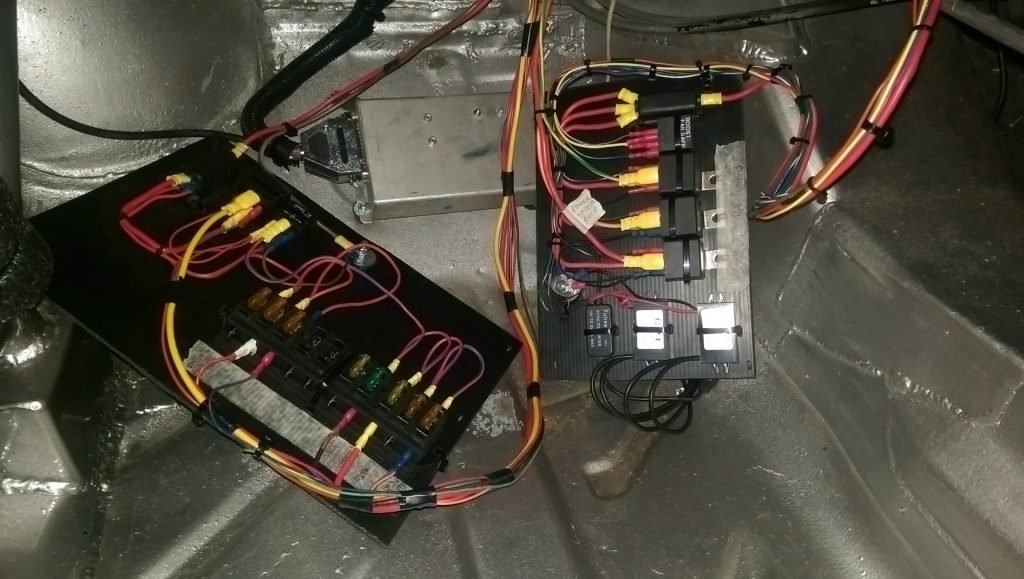
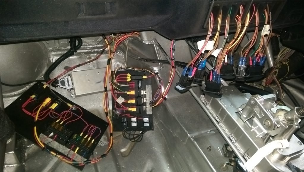
The ECU Fuses and Fuelpump relays. I have a 70A relay to the secondary pump and 40A for the lift pump.
The wires are all long enough to enable the board to be lifted into the footwell for easy testing when diagnosing an issue. 
The multi connectors are fiddly but easy when you`ve done a few.


Camera 12V to 5V USB converters. 

Ancillary relay board and fuse. For Power Steering pump, VAC Pump and cooling fan.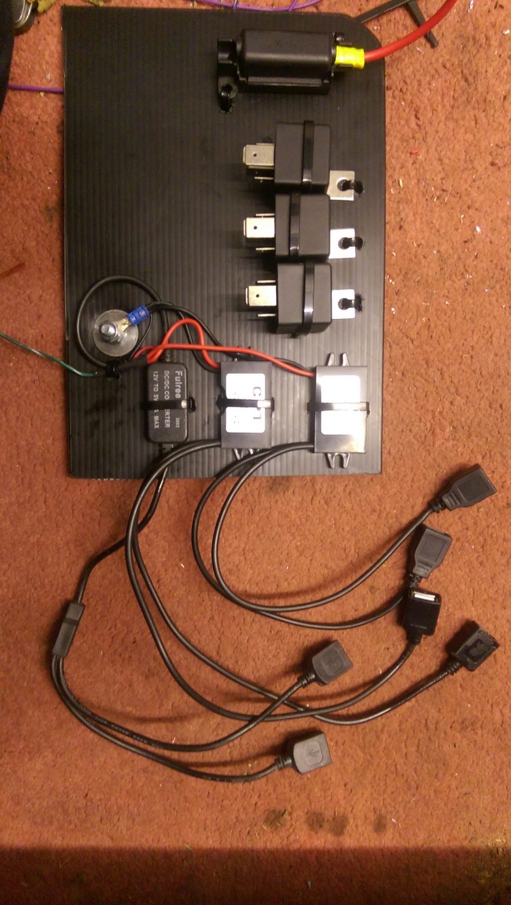
I used the opportunity to replace the Isolator switch with an FIA one that not only cuts the 12V from the battery but Earths everything through a resistor once isolated which is to stop the alternator back-feeding the loom.


Just needs labels for the relays 
The previous loom had short tails going to the dash switches. Whilst his was nice and tidy, it meant it was difficult to remove a switch and test without unplugging it.
The new tails were left much longer. They need tucking out of the way but it makes removing switches to test far easier.

The ECU relay/Fuse board, Ancillary Relay Board and switches all have long wires to enable easy testing but are fastened up behind the dash when in use.
ECU in place, Fuseboard in place. This is obviously just waiting to be kicked by a passenger..

Cover and footrest in place. Not only tidy everything up but stop any accidental damage from passengers. 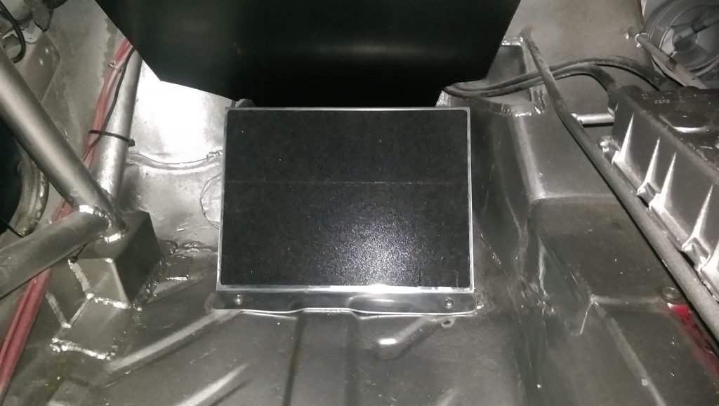
This was tested at Oulton and even though I ran over some aggressive kerbs to highlight any connection issues I didn`t have a single problem all day.
Fingers crossed that`s the end of the wiring problems..