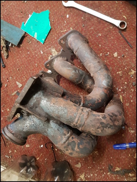
At the Circuit Days event, both Matt and I were sure we could smell some exhaust fumes under the bonnet but couldn`t find the source anywhere. I decided to remove the turbo and check the mounting face as everything else seemed OK. As soon as it was removed I realised I had a problem.
I didn`t take photos before removing the outlet flange, it was hard to show the problem and I was concentrating on finding the issue instead of taking photos.
The manifold has certainly seen a few extreme heat cycles but appeared to be holding up well after the previous repair back in 2015
Closer internal inspection immediately identified the problem. The inside of the collector looks worse for wear. The steel has cracked badly.
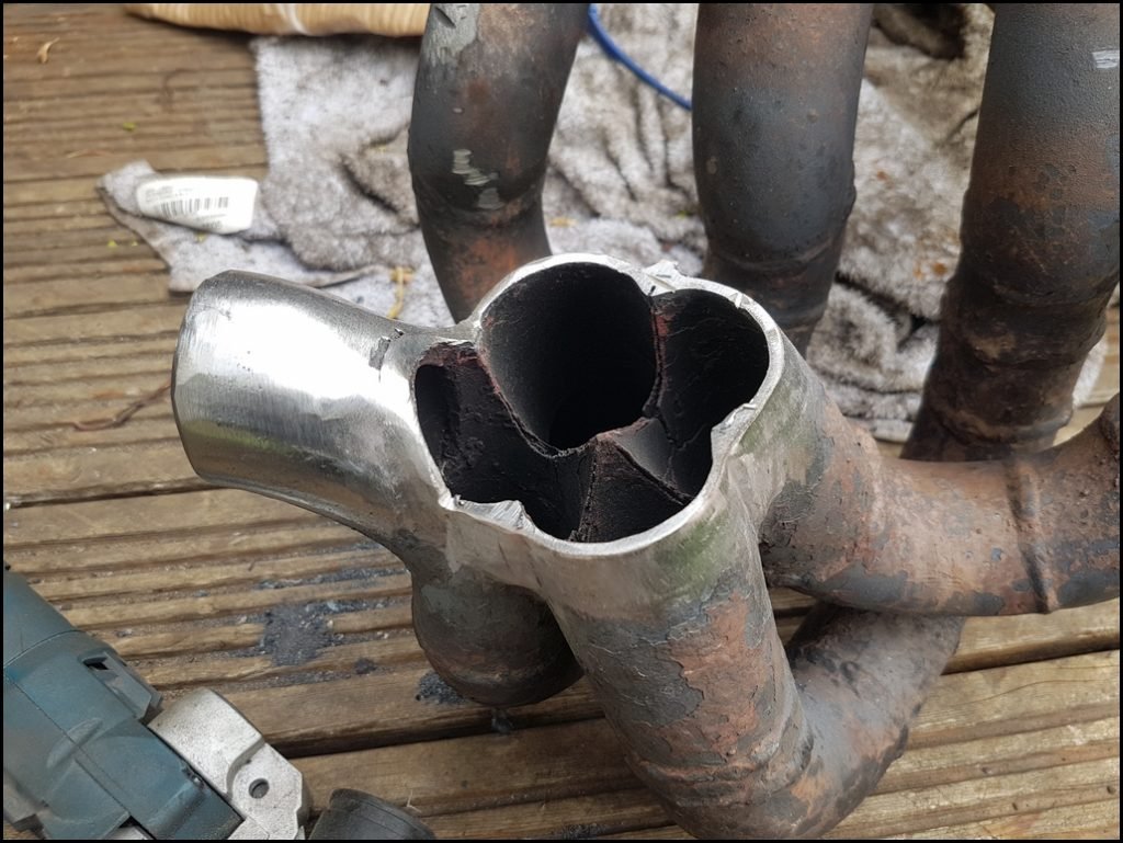
That circular crack highlighted goes clean through the wall of the tube
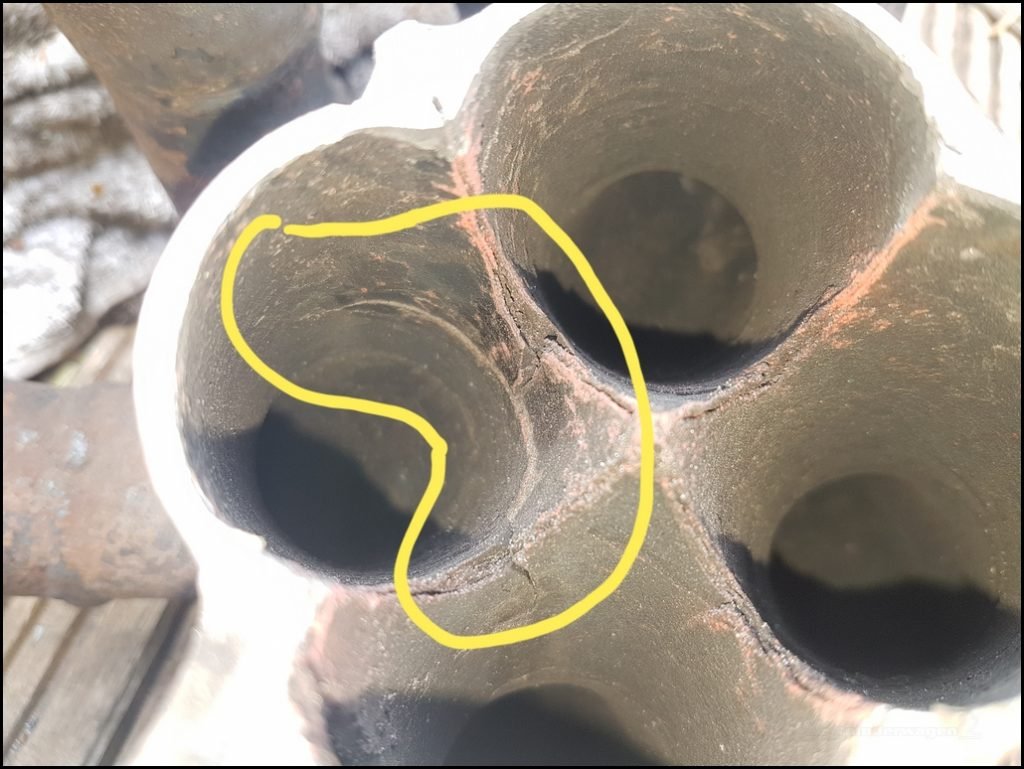

Quick flapper wheel on the outside and the extent of the damage was obvious
This is the outside of the same crack. No wonder there was a smell !
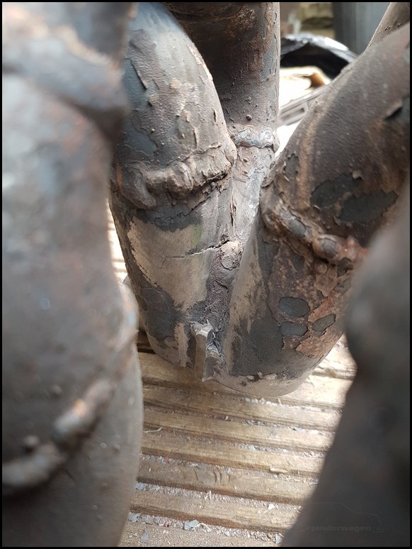
Die grinder to clean the inside and again, it was worse than I initially thought.
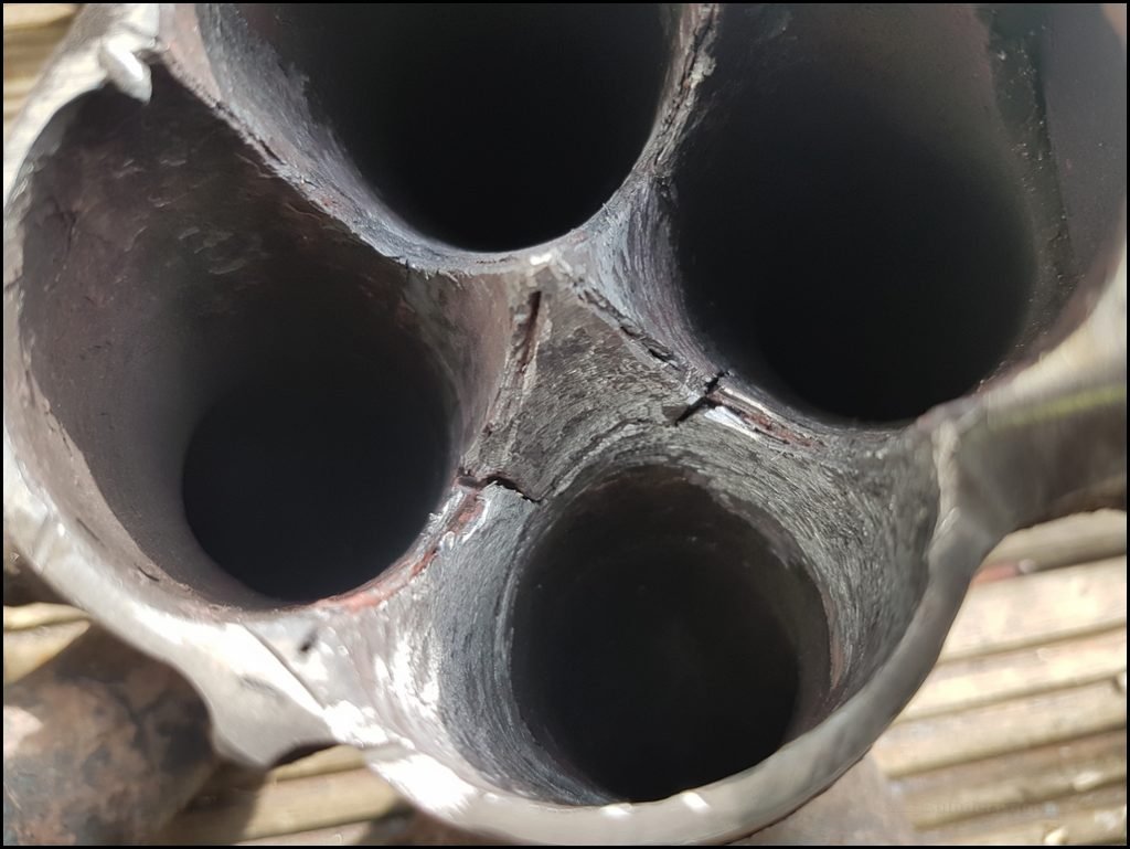
No option but to cut it off, it`s certainly not possible to repair that.
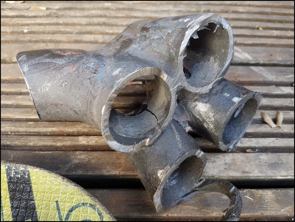
The actual runners from the head to the collector were unmarked, it`s just the intense heat of the collector that caused the steel to overheat, fracture and start falling apart. Rather than remaking the whole manifold I thought I`d just remake the collector. How hard could it be ? 
Very hard as it turned out
When I initially made the manifold, I made the collector first, then built up the runners to the head flange. This time I was having to build the collector in-situ.
Due to 4 years of track use the runner had ‘relaxed’ and when I cut the collector off they all moved a few mm in different direction. This meant fabricating a new collector was going to be problematic to say the least. Each piece had to be cut and manually adjusted in tiny increments until it fit with the existing runners.
I decided to make the collector from Stainless steel. It’s much less likely to fail in the same way as the carbon steel one did.
Cut 4 tubes to length, cut approximate angles with a 9″ grinder and cutting disc

Flapper wheel to clean up the ends prior to welding

Tack weld into 2 halves
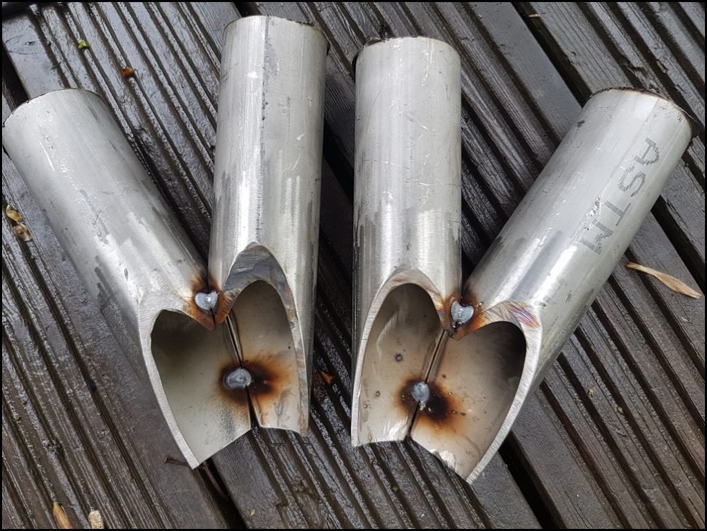
Then tack weld to the end of the runners and fully weld 2 pieces together. I need to start somewhere then I can work backwards from this.
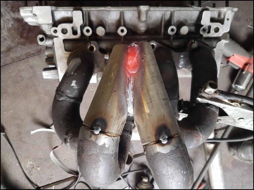
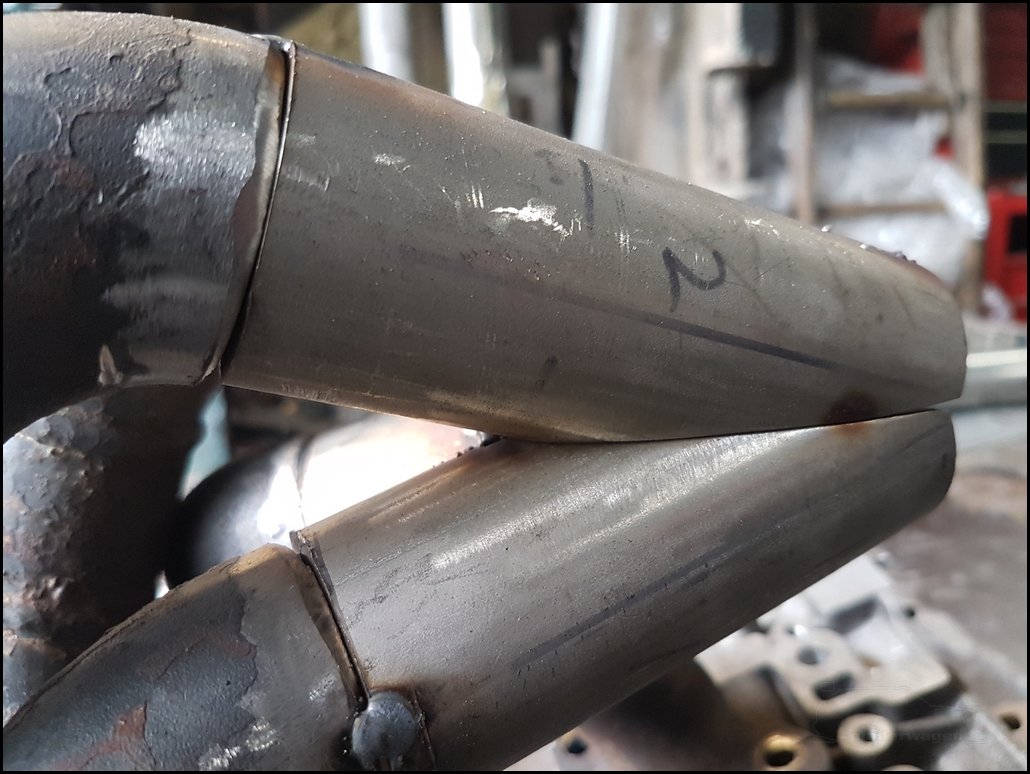
After MUCH cutting and grinding I was able to get the 4 pieces to line up pretty well. This took me several hours of tacking, marking, removing and grinding. I had to make the final 4th piece 3 times as it had to fit the remaining gap which most certainly was not the same as the other 3 
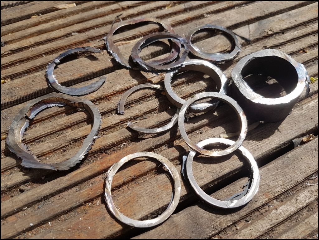
This is a selection of the slivers I had to cut, refit, remove, and cut to get accurate fitting.
The other side was then tacked into place. Once set the collector could be welded up, but the collector was still just tacked at this point..
With the collector in place it was time to set the Turbo position.
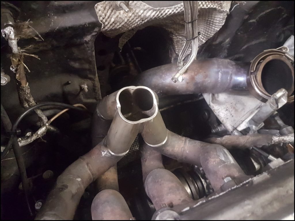
I’ve been contemplating changing the turbo for a couple of years but everytime I think about it, the work required to modify the collector on the manifold made me think it wasnt worth it. The car is quick enough, I won’t use more boost, especially in 3rd and 4th so what’s the point. 
Then this happened and at the same time, I spotted the turbo I’ve had my eye on come up for sale very cheaply.
If that does’t scream “This is meant to be !!” I don’t know what does  Or maybe I’m just trying to convince myself this is a good idea
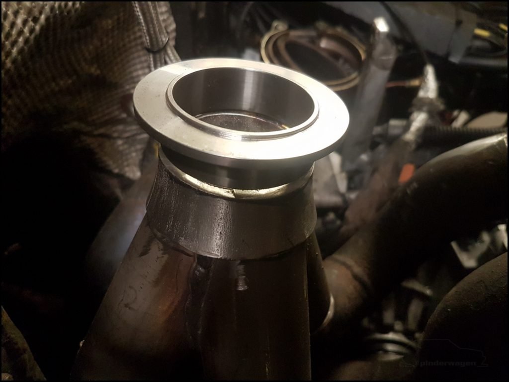
The replacement is a standard Tial V Band, rather than weld that to the collector, I needed to lift it slightly, a 4″ to 2″ SCH40 reducer was cut to suit and was used to join the V band flange to the collector.
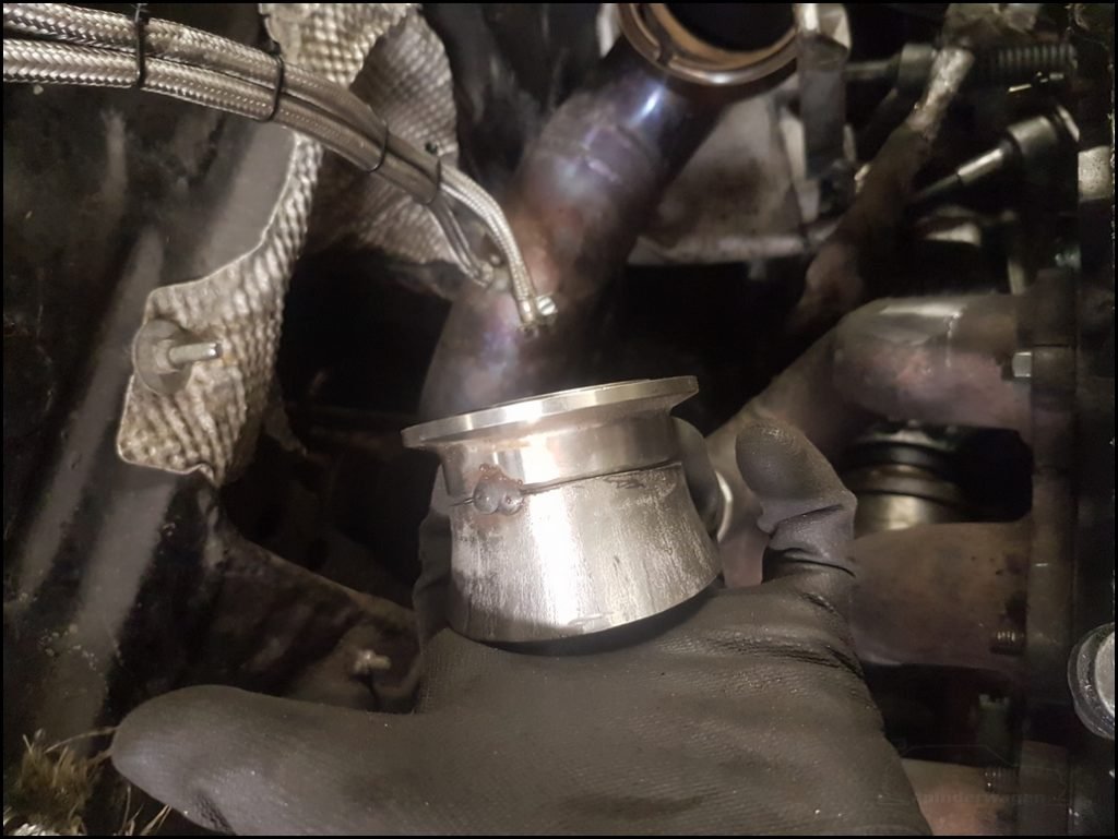
Turbo bolted to the flange before welding and the downpipe tacked in situ. At this point the wastegate isn’t connected to anything, its just in the photo for completeness.
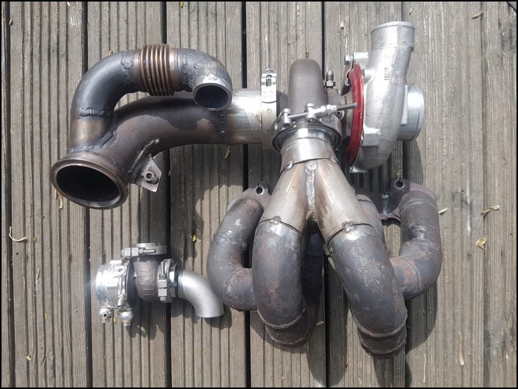
Cut hole in the collector for the wastegate takeoff
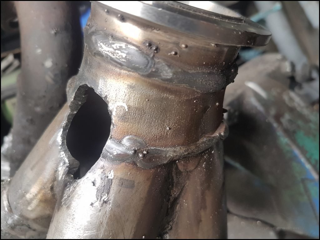
People often just weld a straight piece of pipe 90 degrees to the collector. That seems to work too but I’ve always tried to smooth the flow in the inlet and exhaust system. The elbow was offered up to the cut and ground down to sit closely

Flange welded to the downpipe for the wastegate exit

Turbo 3″ outlet flange welded to the downpipe, it needed a short extension to reach the new turbo

I haven’t cleaned it up at this point Not my finest work I’ll be perfectly honest, but it’s strong and will do the job. There isn’t a hole on the bottom right runner, it’s just a shadow.
The wastegate outlet is also welded in place at this point.


EGT sensor mounting in the hottest point of the collector. If you are going to take a measurement of something, my view is make it accurate and representative or don’t bother.
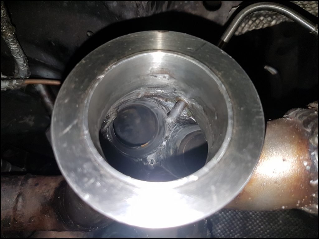
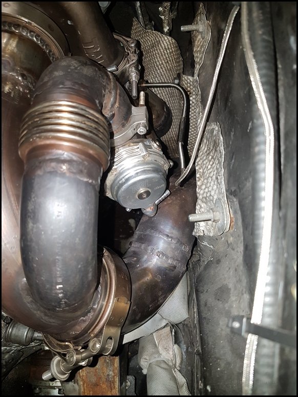
Wastegate in place. It looks close to the downpipe but it isn’t, I can easily fit my fingers between the wastegate and downpipe.

This should last a bit longer than before. The other lasted 4 years so I expect this to outlast the Golf 
