I looked online and spoke to a few place I hoped might have a ready cut exhaust Manifold flange in 10 or 12mm Mild steel. They are worth buying off the shelf for the effort involved. Nobody had one, so I thought I may as well make one instead.
Luckily I had some 12mm plate from a left over project years ago !
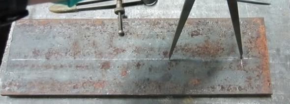
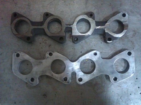
Started using a stock Cast item as a template and a piece of 12mm steel plate.

Mark roughly

Having scribed the centres of the holes, they are then centre-punched.

After drilling 2 opposite holes and bolting the manifold to the flange, I could drill the remaining holes in exactly the right place.

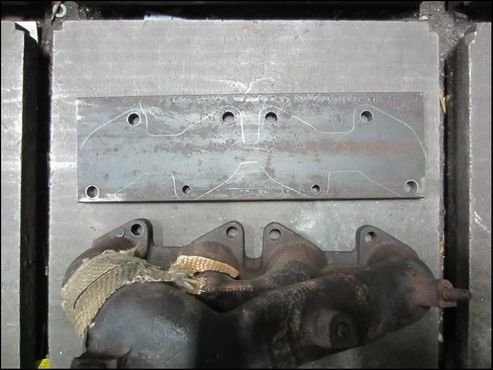
Cut the manifold on a band-saw to end up with just the flange. Bolt back onto the plate and drill some big holes….

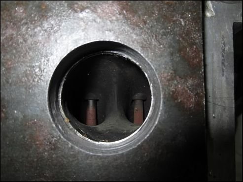
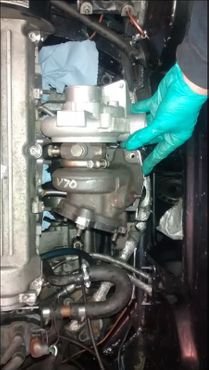
Put new flange onto scrap head and realise something is wrong. 
Put cast flange on head.

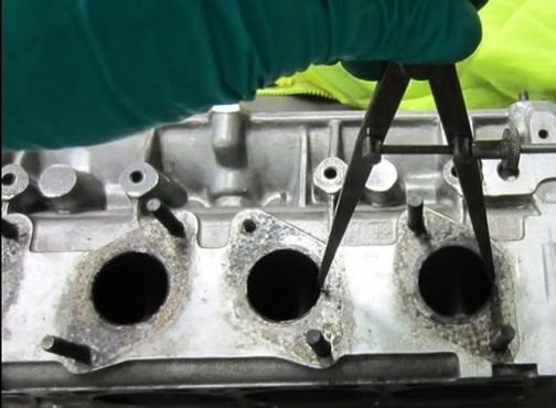
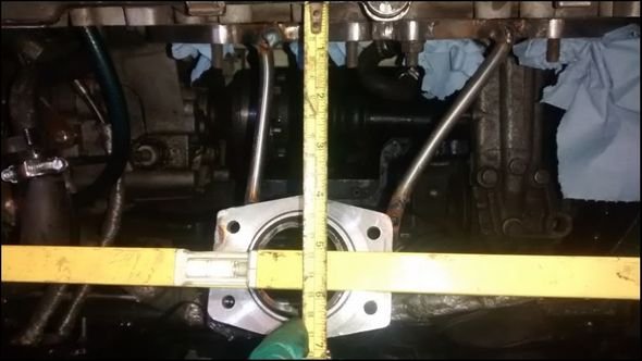
Look closely and realise the original holes don`t line up with the cylinder head !!  The centre 2 holes align well enough, the 2 outer ones are too low. It`s not a case of the stud holes being in the wrong place, without any studs, it`s impossible to position the flange to align all 4 Holes with the head !!
I can only assume every cast ABF manifold is like this. Unless you cut the runners off, you`d never know 

Yes, it`s blindingly obvious now, but I should have checked that BEFORE drilling the holes 
Start again.

Measure hole centres with calipers.
Transfer to plate
Centre punch

Then check again with a ruler. (Measure twice, cut once applies. It should have done the first time too…..)

Double check.
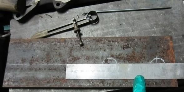
Drill.

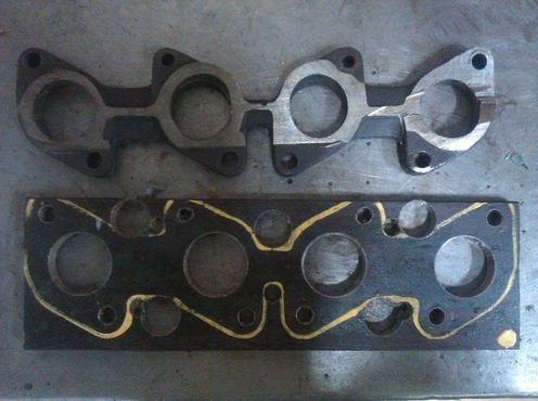
That`s better 
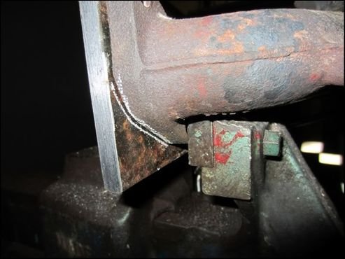
Now that`s done, I need to trim it a bit.
Drilled holes for `internal corners`
First grind.

Finished. I`ve purposefully left it `chunkier` than a stock one. Once the manifold is welded I`ll cut some expansion `slots` in between the cylinders and at the stud holes and trim a bit of material off if I think it warrants it. However, I want to keep it as robust as possible to minimise warping when welding. It will be bolted to the scrap head and welded in stages, so I`m hoping it`ll be OK.
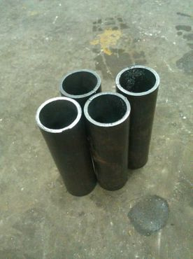
I need a 4-1 Merge collector to transition from the 4 runners to the Turbo inlet.
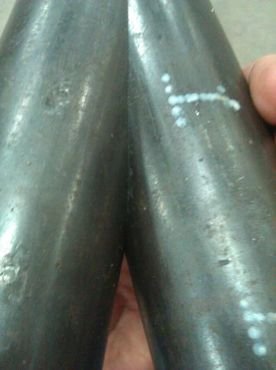
Start by cutting 1 1/2″ SCH40 CS into 4 lengths.
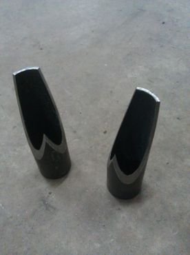
Make a jig to hold the tube at 15degrees and also to be able to rotate it 93degrees between cuts.

First cut, Left on the slowest setting on the bandsaw with plenty of lubricant, took around 20minutes per cut.
Looking sharp !

Lets do another.
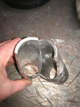
Put the 2 pieces together. Can hardly see the join 

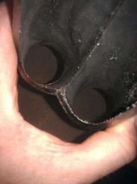
Tack together after cleaning up the metal ready for welding.
Once all 4 pieces were cut and tacked, I could weld it together. 
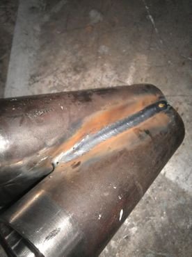
pretty warm…
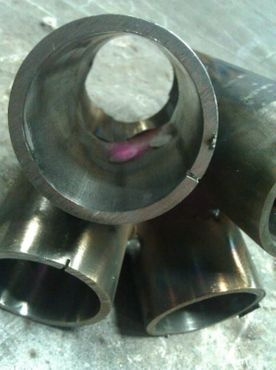
Filling in the middle was a pain without an extended reach welding torch.


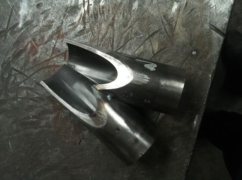
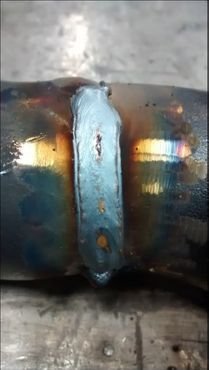
Wire brush the weld clean.

Tidy the inside of the collector with a flapper wheel to remove any sharp edges. I`m very pleased with how well it fitted together


Finished.

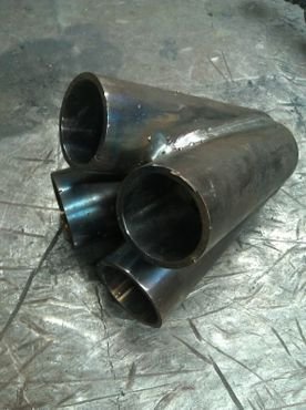

The `outlet` will need cutting to line up with the Turbo flange, I don`t have the Turbo or the Flange yet, so I left them longer than necessary so I can cut them down to fit.
My biggest error was not chamfering the ends of the pipes. I can still get in to do that now, but it would have been easier if I`d done that BEFORE welding it together.
Once I start building the manifold, one of the trickiest bits will be welding the elbows to the ends of the collector, there isn`t a great deal of room to get the torch inbetween the runners. I did practice with a bit of scrap pipe and it is possible, just a bit of a faff.
I`d like to pretend there was no adjustment necessary, but I had to modify the joints slightly with a grinder and flapper wheel to get the 4 to sit together, nothing major but they didn`t fit together perfectly without any tweaking 
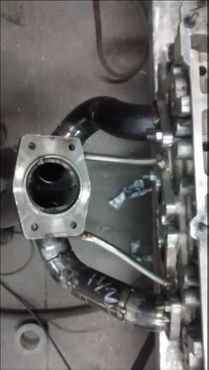
I tried to find a supplier of the manifold to Turbo flange, but had no luck at all. Made one from some 12mm plate, turned down to 10mm, leaving a 2mm `ridge` in the middle. This sits into the turbo housing, giving a much better seal as there is no horizontal path for the exhaust gases to go
To say I hadn`t used a lathe since I was an apprentice, I think it turned out ok…

I don`t have a photo of the flange as I was cutting it out, but you can see it in later photos.
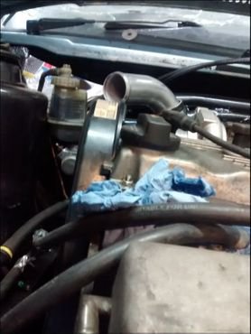
I now spent a lot of time trying the Turbo in varying positions and clocking the inlet housing to try different outlet routes. Some positions caused issues with the actuator linkage
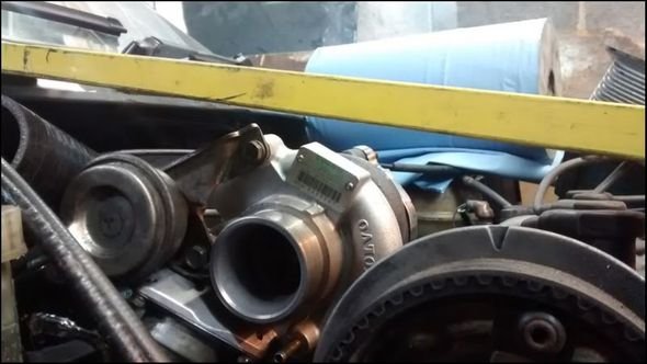

Once I was happy, I double checked clearances. I also allowed enough room incase I `upgrade` to a larger Turbo in future. The exhaust flange would need to be changed, but that`s not a big job. I`m keeping my future options open 
Some tube welded to the head flange and the turbo flange allowed a position to be set


Now came the tricky bit ! It`s not as simple as just welding a few bends, you need to not only look at the route of the runner you are working on, but also where the others will go and try to keep the run as smooth as possible.

Tacks should be in positions easy to access later, I didn`t do that initially, but Gurds reminded me and I tweaked it .
Runner 2, from Cylinder 4. As the Turbo position worked better when offset, they aren`t equal length.
At this point, I wasn`t sure why I didn`t like it. Took me quite a while, but then I realised it`s the straight piece of pipe. If all the runners were made up of bends, it looks much `nicer`. Once I add a straight, even if it`s short, it didn`t look as good. Obviously, once in place, you`ll never see this, the aesthetics are only important at this stage.
Runner 3, a short straight needed under runner 2. At this point, I really wished I had 4 hands. Holding 2 pieces of tube and then trying to put the welding helmet down and tacking was `challenging`. Even using gaffer tape to help hold it.

I checked each band so the nuts could be removed with the manifold in position.


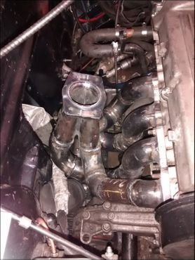
Now it was all tacked, the manifold was refitted to the engine to check all clearances were still good and something unexpected hadn`t happened. Gearbox clearance was good, as was engine mount, steering rack and bulkhead
At this point, I welded all the joints I could see, apart from the runner to flanges. By welding as much as possible now, it meant once the runners were removed and the inaccessible parts welded, distortion would be kept to a minimum.
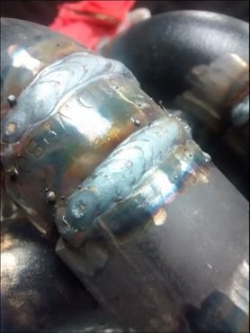
This shows clearly the weld up to the closest runner

Now, the tacks were ground off and the runners removed one at a time. Exposing the `unwelded` part of the joints

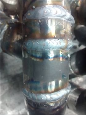
Then they were welded

Once the runner was fully welded, it was refitted to the manifold and the next one removed and welded. Final welding was only done once access was checked to weld the collector to the runner. I ensured the last runner to be refitted was the easiest to weld. Quite a bit of `splatter`, but the welds are airtight and with good penetration.

Amps were turned up to weld the runner to the head and turbo flange. The flanges were both bolted down securely to minimise any distortions.


IF I was going to get this ceramic coated, I`d have ground the welds smooth. I did try it one a test piece and it looked much nicer, but I decided I`d rather leave the welds intact. It might not look quite as nice, but once wrapped, that doesn`t matter and if I happened to have a poor weld, grinding may just cause a tiny leak that I wouldn`t have had by leaving it alone.
I suppose what I`m trying to say is yes, I know some of the welds aren`t pretty… 
The turbo flange was welded to the collector once the collector was trimmed to fit.

I ran a weld around the inside of the flange.

Then ported it to give a smooth flow.
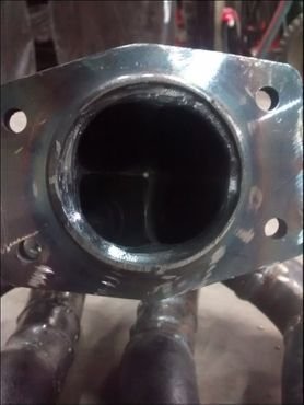
Three of the runners lined up spot on with the head flange

Once didn`t

Ported it smooth

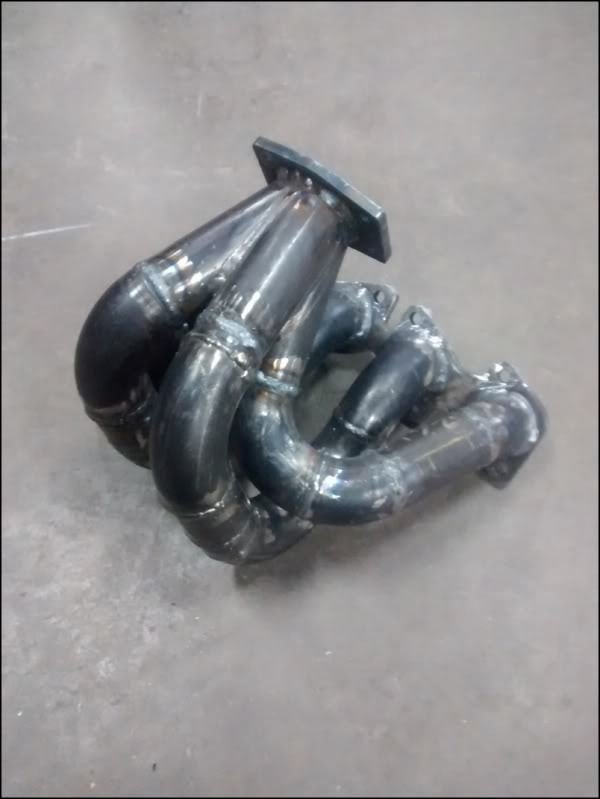
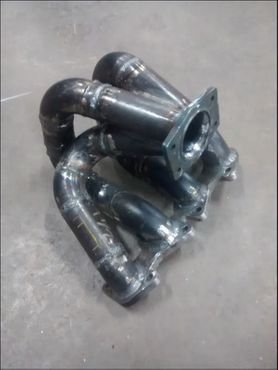
Anyway, here is the finished article.


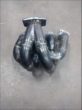


Back to the car.
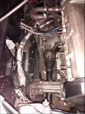
Fit the manifold
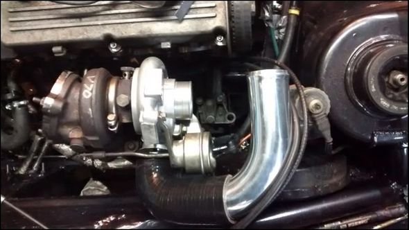
Add Turbo

Fit outlet hose and check clearance.
For V1, I`m very pleased. Yeah, it`s weighty, but it`s certainly secure. In time I may make a Version #2, but it`ll be the same format, just with S/S pipe / bends and TIG welded. I strongly suspect this will never happen, but you never know…
Before fitting, this was flushed through with some petrol to remove any loose debris, then left for a few days to ensure it had evaporated.