In very simple terms, a suspension damper is a piston within a cylinder that has restrictions inside to slow the travel of the piston. For the sake of this explanation, I will assume the piston sits in the middle of the travel when the car is at rest at standard ride height.
This leaves 50% of the total travel available when under compression or when extending. I`ve only shown the travel under compression.
If the car is lowered and nothing else is changed, the topmount moves towards the hub which lowers the piston in the damper when the car is at rest.
This reduces the amount of travel the piston has available so when the damper is compressed whilst driving there is a far higher chance it will bottom out in the cylinder, effectively making the suspension solid until it extends again. This is obviously not something you want to happen mid corner.

If the topmount it raised in relation to the chassis, this will move the piston back to the centre of the damper even though the car itself is lowered. This diagram also shows the ball joint extenders fitted.

I`ve overlaid the original damper position in pink to show what I mean.

This is something I`ve been meaning to do for a while and once I fitted the Balljoint Extenders I was able to lower the ride height to a level I wanted whilst maintaining an acceptable roll centre. This reduced the damper travel and would have caused bottoming out of the suspension if I didn`t address it.
BC & some TEIN Coilovers allow moving of the lower mount to set the damper position and this removes the need to raise the topmount. The KW Clubsports I have fitted have fixed hub mounts so I needed to do something else.
After accurately measuring the position of the original top mount from fixed datum points, I cut off the top of the suspension turret
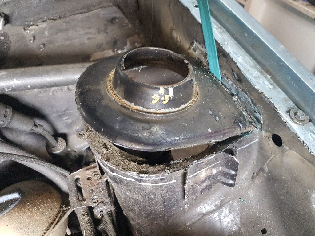
Top removed. The factory sealant is still in place and there is no rust at all !

Clean off the sealant with a wire wheel on an angle grinder. Highly effective but bloody lethal. I always end up picking bits of metal out of my clothes after using one of these. Goggles are a definitely needed

Sourced some 3mm steel plate from a local stockholder

Bend the strip to sit inside the original tower by pushing against a bit of pipe in the vice then keep tweaking with a rubber mallet to get the correct shape


Lay the plate on top, then mark the underneath to get the correct profile. The piece of wood is to ensure the strip is wedged tightly in place.

Cut the plate and trim to get a snug fit. Whilst I am going to be welding on both side, it always helps if the gaps are minimised so they don`t need filling with weld.

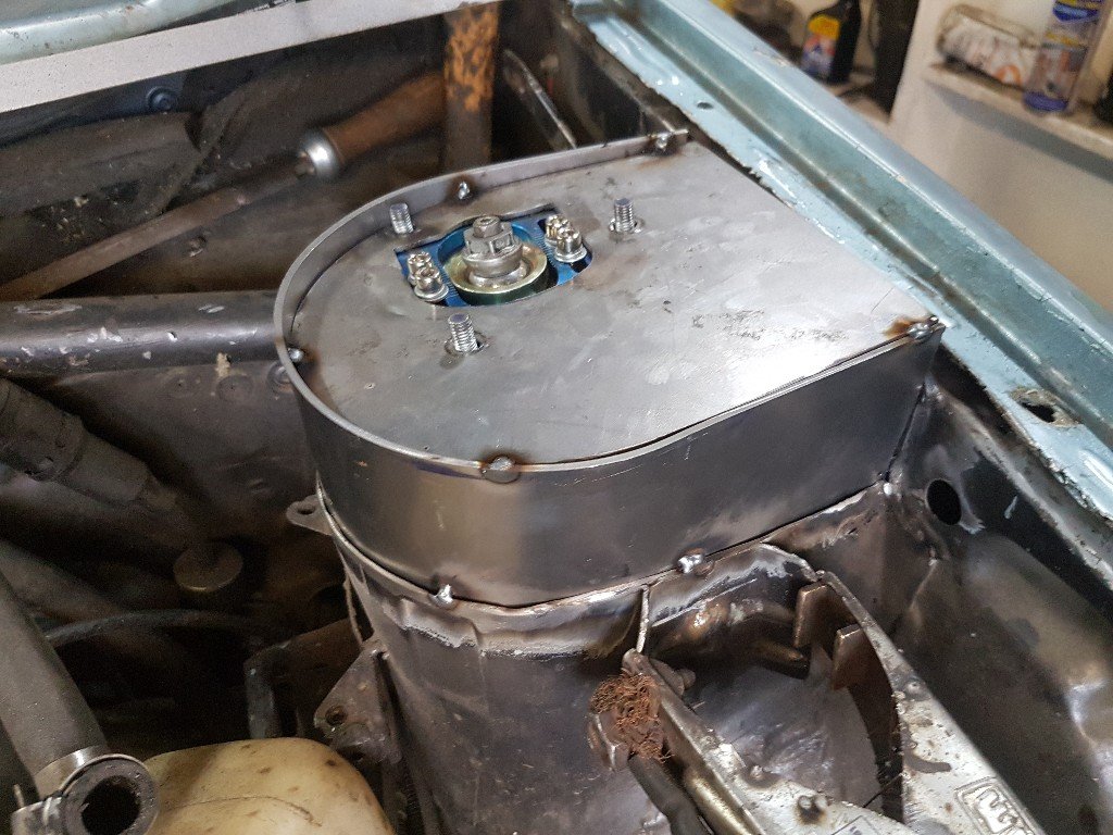
I then marked the plate to allow the topmount to fit. Initially I placed it in the same position as the original, but as the photos show, I changed this later.

Chain drill then clean up the hole. A holesaw would have made this far easier, but I didn`t have one the correct size.

Tack everything in situ, then measure from the previous datum points to ensure the topmount is accurately positioned, adjusting as required.

Turn up the power on the MIG and weld the plates together.

Around this point I realised I can gain some extra caster by moving the topmount towards the bulkhead so made another top plate with the mount moved backwards.

I then welded the plate to the chassis, inside and out.
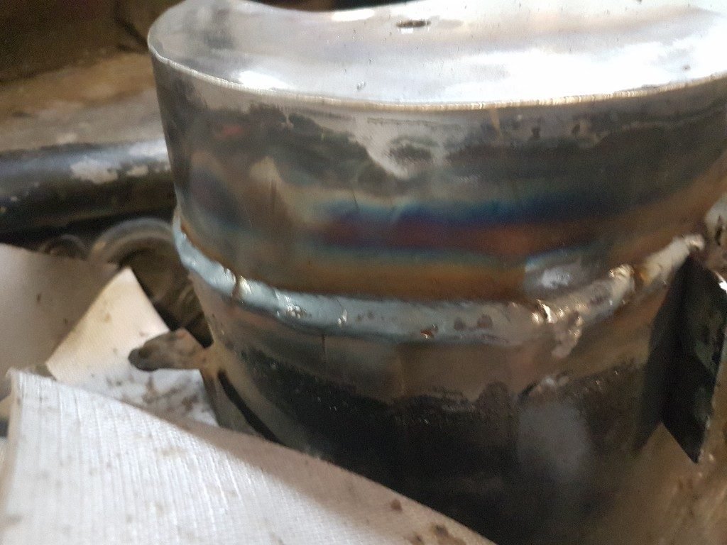
Weld along the inner wing to secure the outer edge of the plate with a 3mm piece of steel.
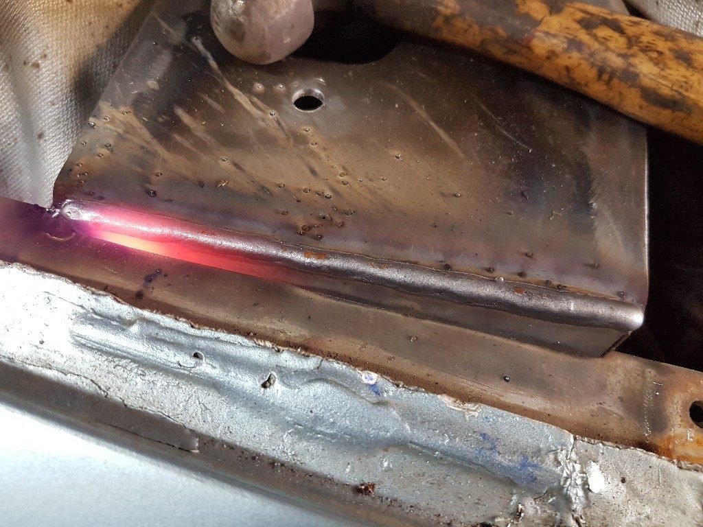
After welding dress the welds with a flapper wheel on the grinder to smooth everything.

Covered the area with a dust sheet then gave it a quick coat of primer, refitted the suspension to move the car.

Then removed and added basecoat and laquer.

Suspension and ancillaries refitted.

The spherical bearing in the top mount was catching under full lock. Initially I wasn`t sure where but after close investigation I spotted where it was touching. Due to the increase in caster, the spring platform was just touching the spherical bearing retaining ring at full lock.
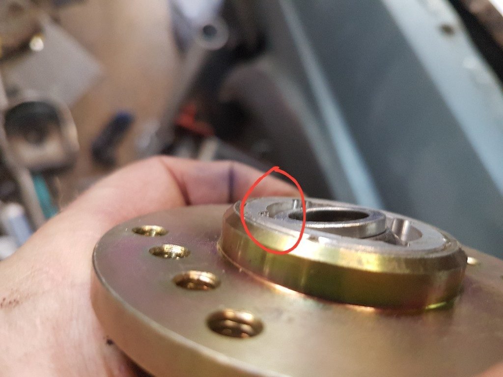
By carefully rotating the bearing and grinding away part of the aluminium I was able to gain the necessary clearance. This is only to hold the bearing in place, the load is on the top of the housing.

After completion I built it all back up, set the ride height and then had a 4-wheel alignment carried out where I was able to get over 7 Degrees of Caster per side. Bear in mind the standard caster for a MK2 Golf is only 1.5Degrees. The modifications I`ve made to the wishbones and topmount location have given me a huge increase.
This means when adding lock, the outside wheel gains negative camber instead of rolling over towards vertical which is much more desireable on a track car !
This video shows it clearly, at first the steering wheel is turned to the left and the right hand outer wheel increases to 4degrees negative camber, then turning to the right and the left wheel does the same 
I was also able to set the ride height to the desired level whilst positioning the damper at the correct point of its travel when at rest. The whole job took a day and a half but it was well worth the effort.

