A couple of years ago I added some Sill jacking points to the Golf, the long term plan was to use something like these sill stands to be able to work under the car, swap wheels diagonally etc.
With the flat floor and side skirts I can`t use a normal axle stand, there is nowhere to put it under the car.

I`ve seen this sort of thing online and thought it was something I could make myself
Drew up a simple design on sketchup.

This quickly morphed into a more detailed drawing with wheel nut shelf and personalisation.

I’d drawn it at the correct thickness, allowing accurate modelling and exploding of the drawing.
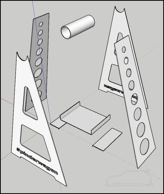
This is what they should look like when finished…..

Initially I thought about cutting it myself but it took around 0.5 seconds to realise that was a non starter  Not only was it a LOT of cutting, there was no way I’d get the detail and accuracy I needed.
Next was getting some prices for waterjet cutting and laser cutting. Who knew so many businesses were that busy they wouldn’t even bother to reply with a quote !
I’d never had anything cut before so was unsure of the process, after several emails I found LASERED COMPONENTS to not only be very quick to reply to my queries and offer suggestions, but they were the cheapest by quite some margin.
I always thought this sort of thing would be too expensive or not suitable to a small custom job like this. Turned out I was wrong !
I created a 2D outline drawing from the 3D model I’d been using, the A frame, shelf and feet was in 2mm Mild steel
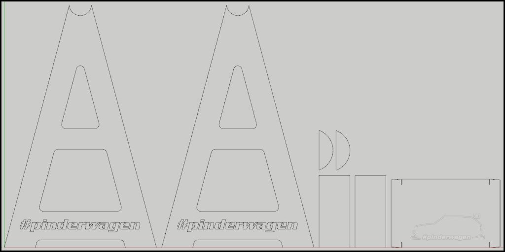
The sides were 3mm

I ordered 4 x of the following and another £20 of various other steel and aluminium pieces I wanted. They have a £50 minimum order.
I really can’t recommend them enough. 

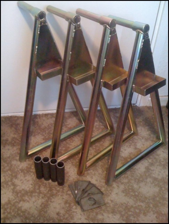
A week or so later the following arrived !

I actually ordered a spare A and side piece to practice on. I’ll be honest, it was pretty cool seeing something I’d drawn arrive in steel 

The 7 pieces of the stand on the computer

The same 7 pieces in steel.

The slot and tapered ends on the shelf will be explained later.

Quick mockup with a couple of welding magnets to hold the sides in place.

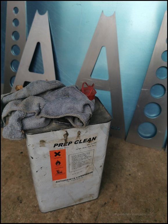
Before welding I gave it all a clean with panel wipe
Tacked the A and side together

Checked the side was at 90 degrees

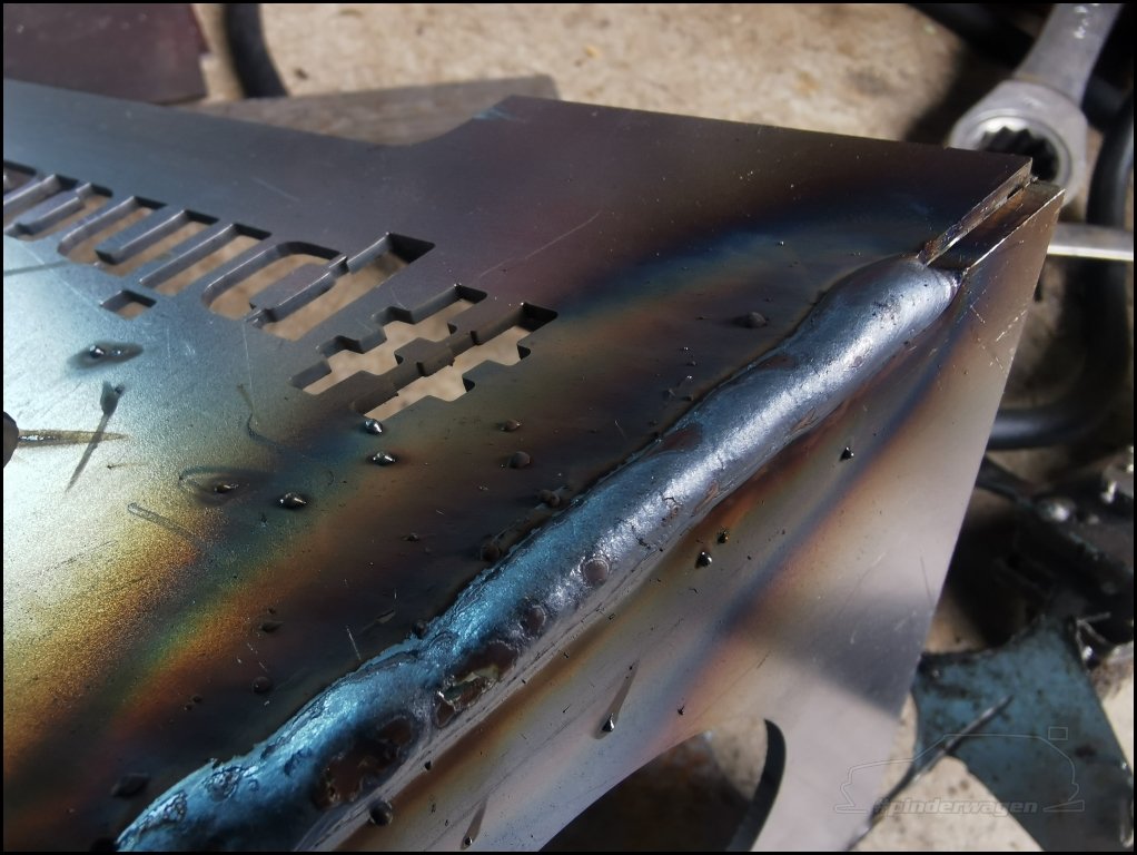
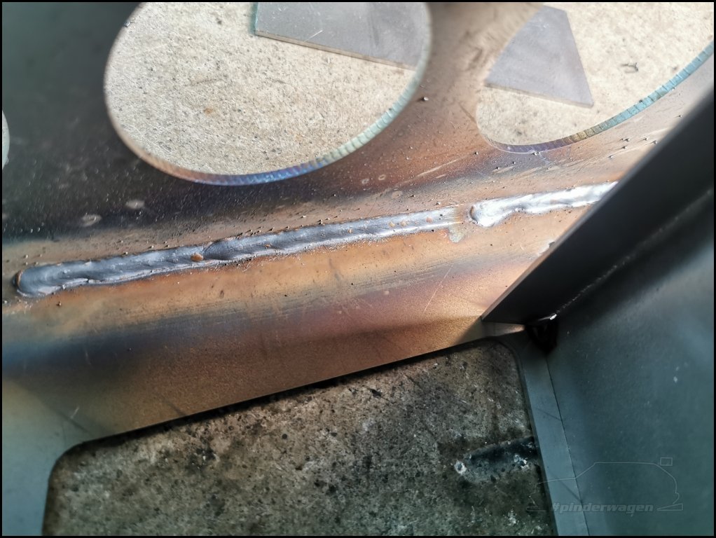
The initial plan was to weld the external corner, I noted each welder setting for a short run. eg, Power 5, Speed 4.5 on the left.

The bead on the outside was OK, but a bit of splatter can be seen which would need cleaning.
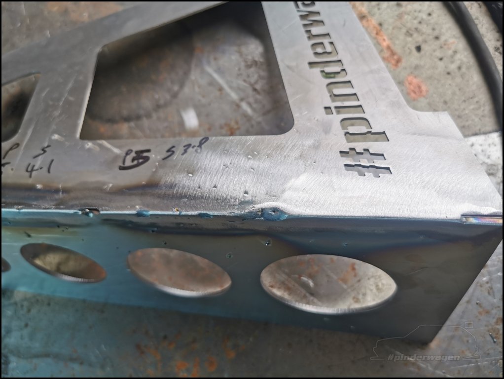
I then ground it back with a flapper wheel to check penetration and finish. Not only was that quite time consuming, it introduced an opportunity to take too much metal away and spoil the finished product. The welds on the left had insufficient penetration.
Next I tried welding on the inside, this was FAR easier.
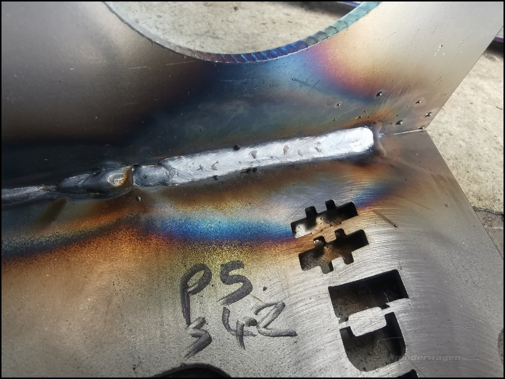
The accuracy of the lettering cut-out is spot on.

Tacked up just to check it all fits as expected.

I had to weld in short runs, positioning the torch through the triangular cut outs and looking through the holes.

Pretty happy with that.
The slots I had cut in the shelf are markers for bending, I line them up with the vice jaws and tapped the ends over 90 degrees.
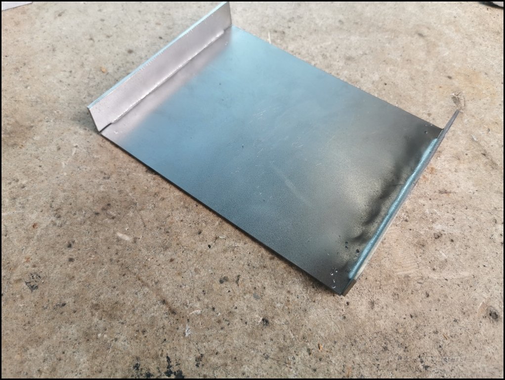
The taper on the end matches the slopes of the A frames

So when fitted inside the frame, no filling / grinding is required.

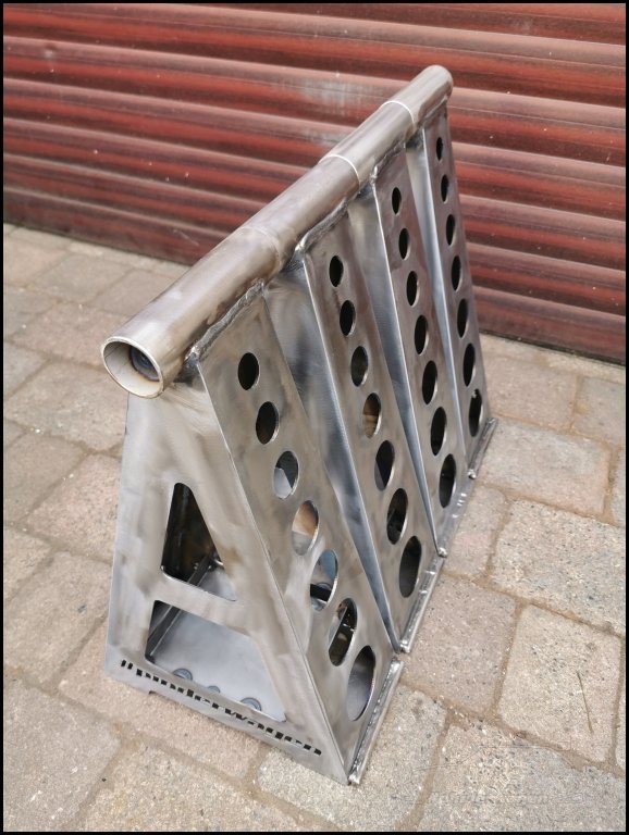
Sides fully welded, shelf tacked.
Next up was the 1 1/4″ tube to sit on top of the frame.

That’s the benefit with laser cutting, everything fits and you end up with a horizontal top with no effort.

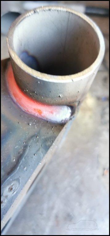
Tube welded to frame.

I set the radius of the cut to be 0.5mm larger than the tube to give me plenty of penetration when welding.

Next up was a stainless bar to one side of each frame, the reason for this will become clear later.

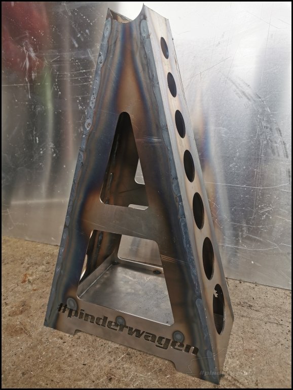
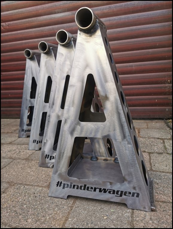
Finished and ready for painting.

Repeat 3 more times
Quick clean up with a scotch brite disc on the angle grinder to remove and contamination and smooth off any external weld protrusion.
Coated in etch primer
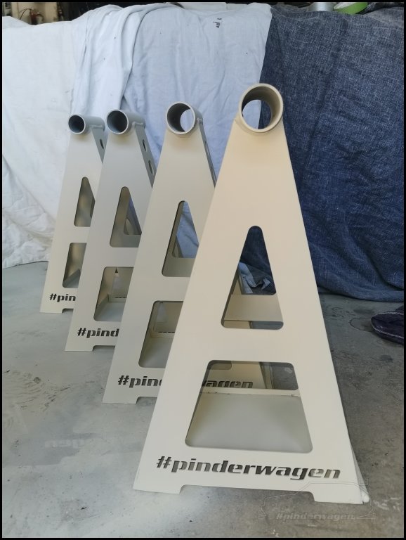
2 in etch, 2 in RAL 2004 Pure Orange

All painted and clearcoated. Now you may be asking “why orange !?”. Quite simply, I’ve found people wandering around the car in the paddock seem to have their eyes closed and I’ve lost track of the number of people who have walked into the splitter and diffuser  Now, they have no excuse for not seeing these !
From this
To reality.

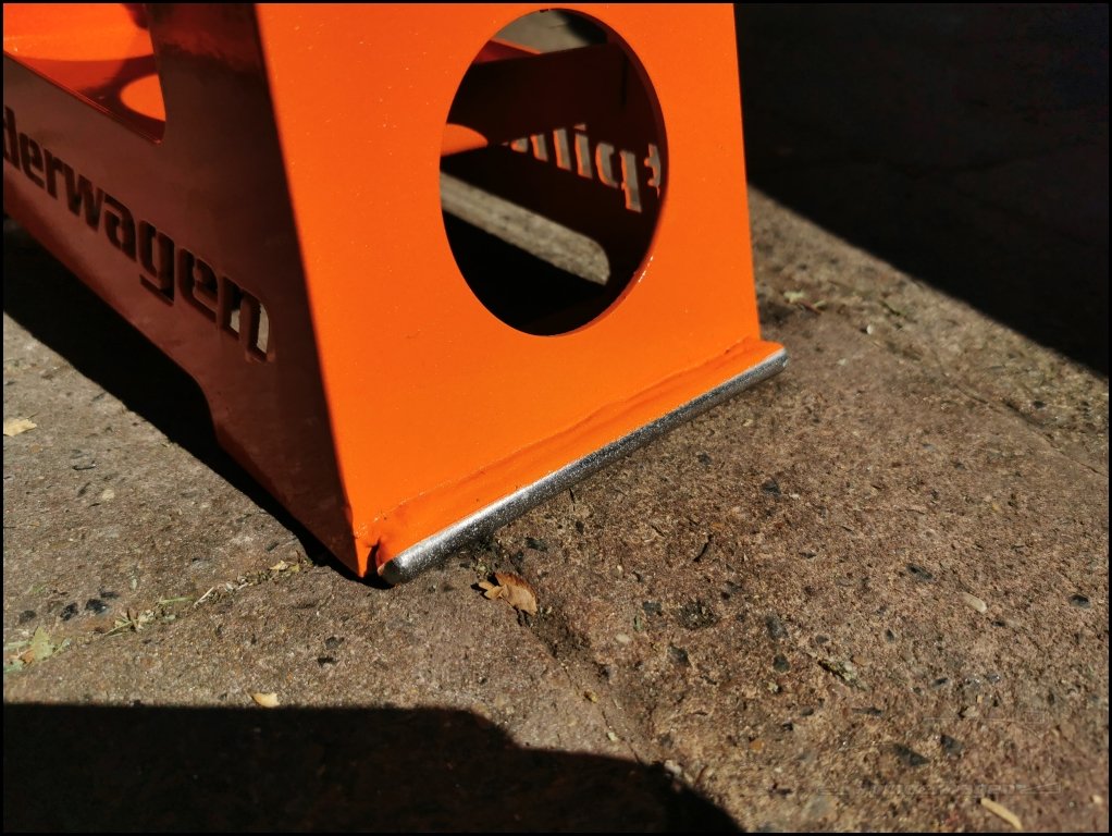
I left the stainless rod part exposed. This is the bit that scrapes along the floor during lifting and if painted, it would scrape the paint off anyway.
The jacking rod is 35mm bright steel. I needed a way to ensure this didn’t slide off the jack, so drew up some 3″ tube and a couple of infill pieces.
Tigged up without filler rod, I just chased the pool along the joint.

They look long and they are, as you’ll see shortly, there is a reason for that.


4x shorter rods with end stops.

To save pedestrians shins, these were painted yellow. Bright yellow…

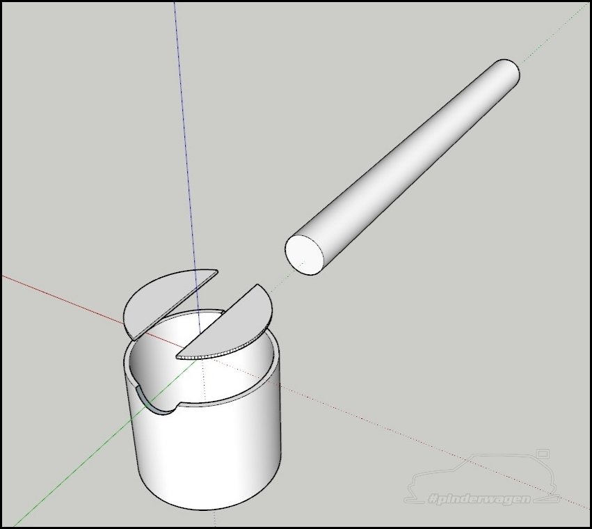
Next was a removable jack high lift tube.
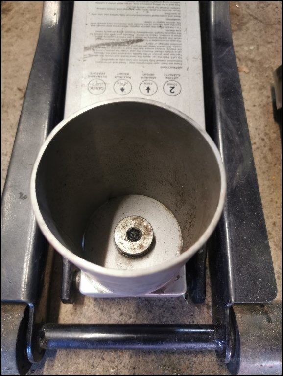
Removed the centre countersunk nut holding the lifting cup to the jack, cut a plate and welded on a boss.
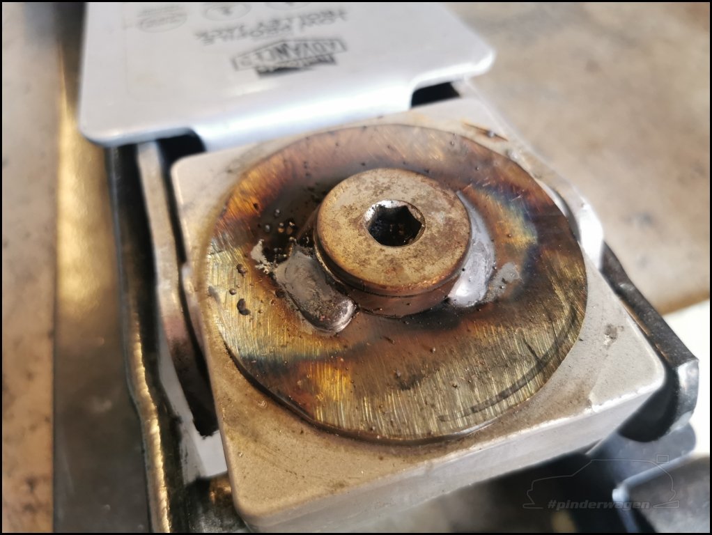
This is a snug fit over the centre stub on the jack.

Weld 3x captive nuts to a plate at the other end.

The captive nuts line up with the countersunk holes I drilled in the lifting cup.

The tube is fastened to the jack using the original large coutersunk bolt.
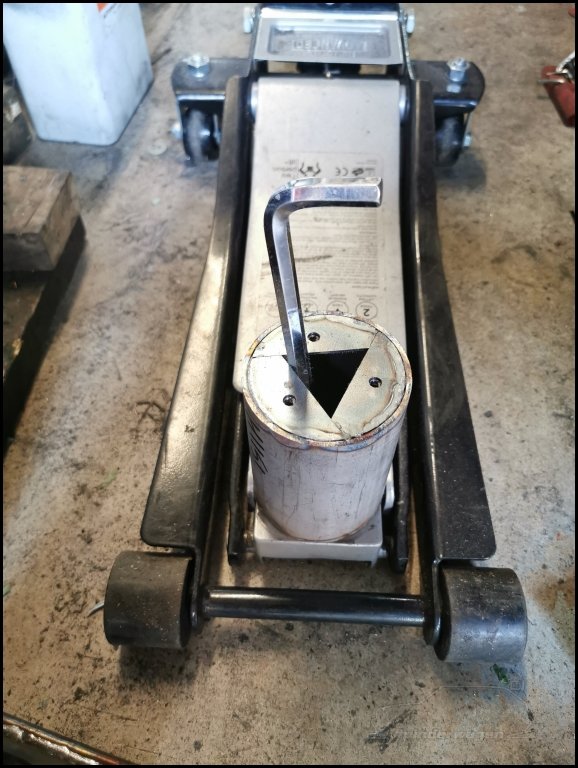
The cup is then fitted using 3x countersunk bolts. By doing it this way I can easier revert back to the standard height by simply removing the extension tube and refitting the lift cup to the jack.

So, after doing all that, how do I actually use them ?
1) The stand is slid onto the long rod and sits between the jack and the tube on the car
2) This is laid flat, then the car lifted and the stand rotates until it’s sitting vertically (see the need for the stainless wear rods now ?)
3) The rear stand and support rod is fitted.
4) Repeat for other side.
This can be left and wheels swapped etc, but if I want to replace the long rods with short ones, I lift the car from the now accessible subframe until the frames are off the ground and swap out the long rods for short ones.

Finished. 
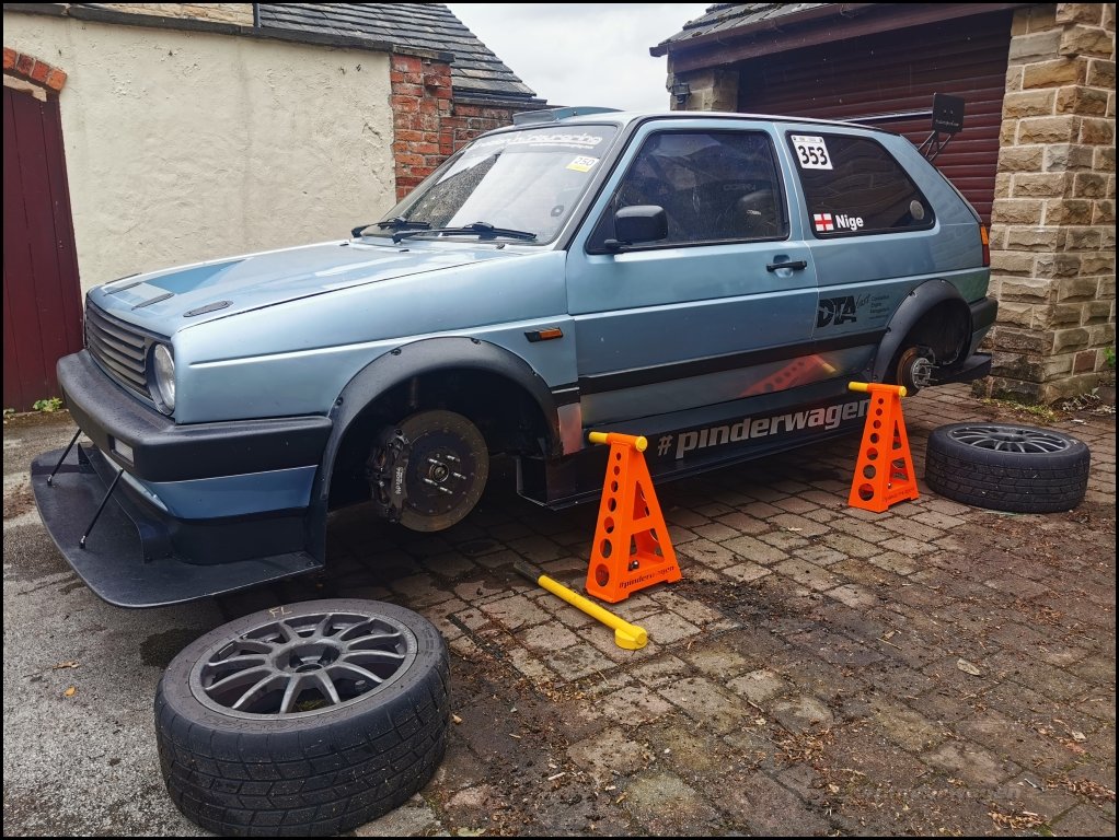

The eagle eyed may notice the front frame isn`t sitting flat on the floor. The sill tube I fitted the other year is a slightly larger diameter and allows the rod to move whilst lowering. A second person can hold the frames vertical if necessary. It does not affect stability.


As my first foray into the world of laser cutting, I get it. Not only is there no way I could buy the materials and cut the shapes for the amount I paid, it would have taken hours and even then I couldn’t have added the extra bits like the #pinderwagen text.
With the time taken to create the drawings, it isn’t something I’ll use often, but for a project like this I certainly would.
Each stand is 3.5kg and when the car is on all 4 it is rock solid. Trying to rock the car by leaning and pushing it has no effect, it doesn`t move at all.
Somewhat surprisingly I`ve had a few messages from people asking if they can support me in some way. I`ve set up a buy-me-a-coffee page for those of you who would like to do so, it allows the opportunity of making a small donation towards future Golf development  .
.![]()