Why Plywood ? Well as I`ve said before, it`s cheap, easy to form and does the job.
A friend commented that the McLaren 650s GT3 championship winning race car uses plywood behind the front wheels and leading to the doors. If it`s good enough for a works McLaren GT3 car, it`s good enough for a MK2 Golf 
I needed a new splitter after breaking the other one at Brands….
I`ve been modifying the splitter with every version, I`m probably up to V5 or 6 now… 
I wanted to improve the ducting to the brakes so thought I`d try a `stepped` airdam…
12mm Plywood, cut to shape and painted with several coats of Varnish then Black paint. First vertical fence fitted.

Add the `main` airdam with an opening cut out and recessed.


I then rivetted the old fibreglass ducts to the back of the rear opening, sealing it off along the top and sides


The IDEA is that air hitting the airdam will move sideways across the face of the dam. The `scoops` will then direct it into the ducts adding a LOT of cooling to the brakes.

By having the stepped airdam, I also increase the effective length of the splitter but without any further overhang. ie it`s as deep as before, but more of the splitter is visible and effective.
Next up after fitting some grilles to cover the old fog light holes was to sort the fence ahead of the wheel

I made some 1mm aluminium side fences to join the vertical fence, but left an opening in the bottom corner with a directed airflow out of it. The aim being to direct air away from the wheel well, reducing the wheelarch pressure rather than adding to it.

Added the stays and stood on it. It didn`t break…

Did some `tuft testing` at Donington.


It appeared to do exactly as I hoped

I`ve added different coloured arrows to show the airflow in various places. There was a clear flow into the brake ducts and a low pressure turbulent area to the right of that (look at tufts tot he right of the green arrows)
This isn`t the most Aesthetically pleasing version but it is certainly the most Aero effective. Front end grip at speed was fantastic at Donington as I`ll explain later 
From a distance I don`t think it looks that bad

I also refitted the flat floor. I`m still hesitant about fitting the full floor and boxing in the exhaust. Whilst it will be more effective, it made the tunnel pretty hot before !
Whilst the car was jacked up I tool this pic. I`ve cut the old Aluminium floor in half and added a vertical bend to give fence either side of the exhaust. I`ll live with the centre being turbulent air, but hopefully by having the fences it will separate the linear air flowing along the rest of the floor.

In effect giving me to large `channels` either side of the central exhaust leading into the diffuser

The air that is caught by the central `scoop` is pushed down this channel

Looking from above, you can see the air is forced through the channel and then the duct hose is connected to this which is then secured to the back of the brakes, hopefully directing lots of nice cool air from the splitter into the brake discs 

This splitter was damaged when a failed tyre broke the front bumper and splitter.
Bought a new splitter, just needed trimming to fit 
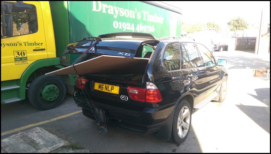
Traced the old splitter, flipped it over to get the drivers side radius
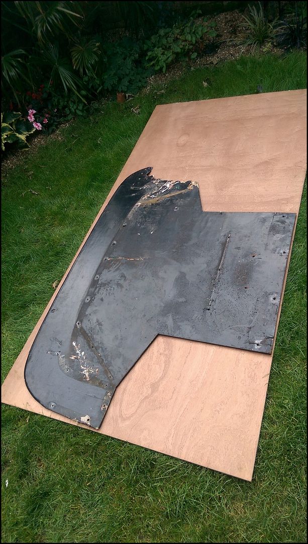
Oh, it`s a bit longer than before. 
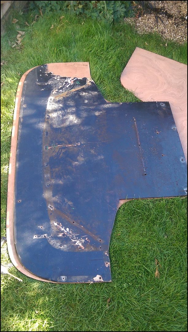
Repaired the damaged airdam and fitted to splitter once painted
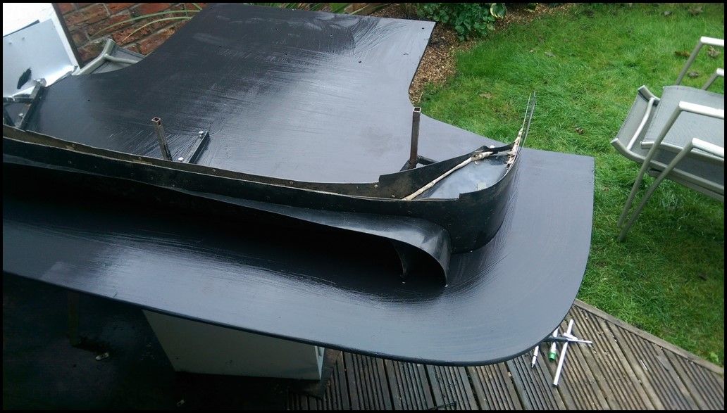
`New` bumper sourced
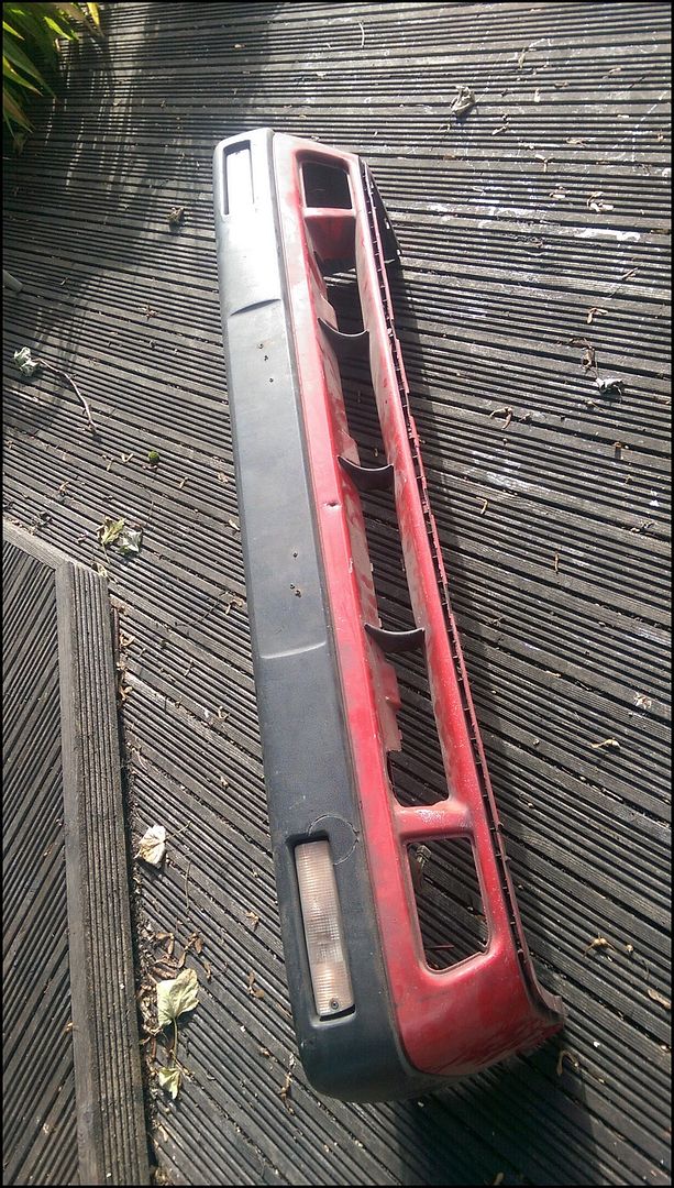
Bumper painted and all fitted. Just needs some mesh ordering for over the central cutout.
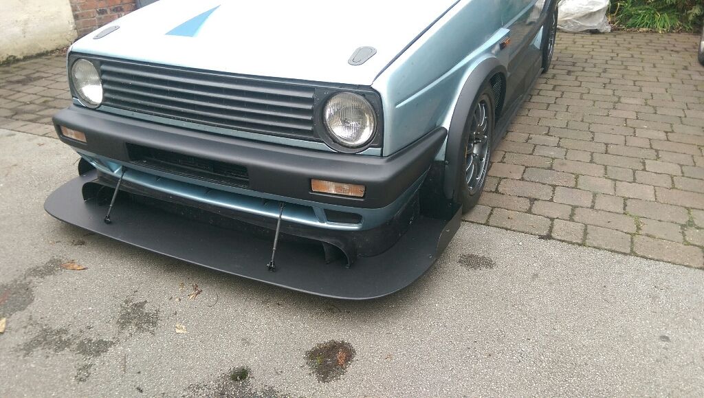
One of the first splitters trimmed down when I had no rear Aero

A bit longer
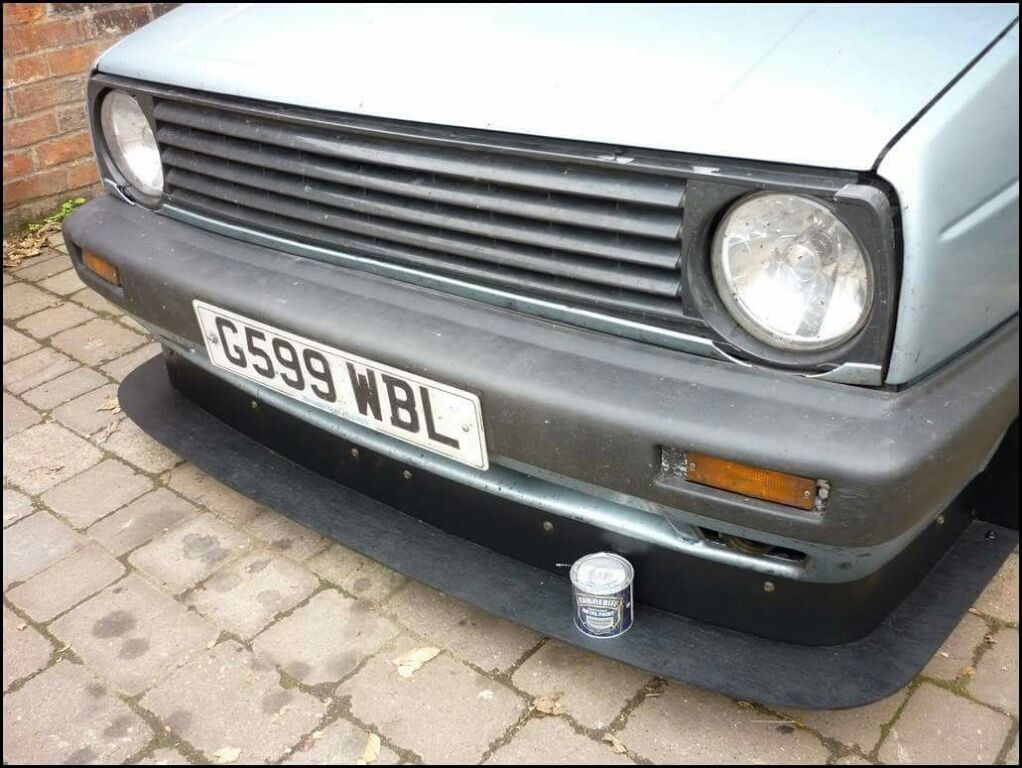
The current one 
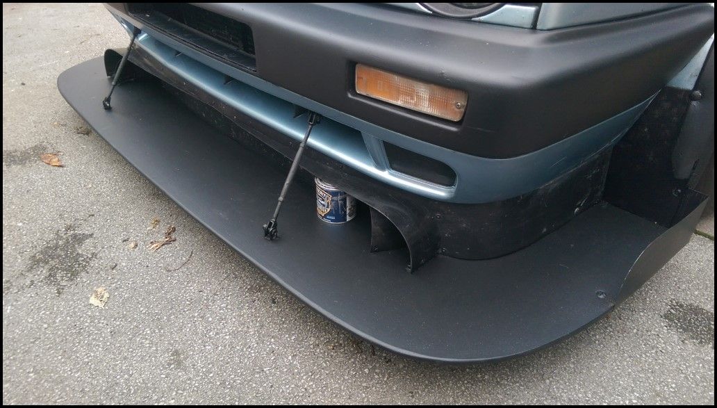
The splitter as it is now, October 2016
The final test. It needs to be strong enough to easily take my weight.
After Rockingham the water trails were showing the airflow wasn`t going fully into the outer duct via the 2nd scoop. The one nearest the airdam was getting a good amount of air, but the air further towards the front of the splitter was coming off the inner scoop and across the fact of the outer inlet before joining the air to the side of the splitter. (Red)
I added an outer shroud to the secondary scoop to hopefully capture the air that previously passed across it`s face (Orange). At the same time I added a second duct tot he back of the rotor which is fed from the smaller inlets towards the centre of the airdam (Green))
A few closeups showing the current configuration.


